Abstract A Flexible Framework for Hardware-Accelerated High-Quality Volume Rendering

A Flexible Framework for Hardware-Accelerated
High-Quality Volume Rendering
Christoph Berger?Markus Hadwiger?Helwig Hauser?
VRVis Research Center for Virtual Reality and Visualization
Vienna/Austria
http://www.VRVis.at/vis/
Abstract
Because of an enormous development of graphics hard-ware and the invention of new rendering algorithms in the past it is now possible to perform interactive hardware-accelerated high quality volume rendering and iso-surface reconstruction on low cost standard PC platforms.
In this paper we introduce a framework that integrates sev-eral different rendering techniques which signi?cantly im-prove both performance and image quality of standard tex-ture based rendering approaches.Furthermore the most common graphics adapters are supported without addi-tional need for setup as well as several vendor-dependent OpenGL-extensions like pixel-,texture-and fragment-shaders.Therefore it is easy to compare the varying re-sults of different rendering algorithms on diverse graphics adapters with respect to quality and performance. Keywords:volume rendering,volume visualization, graphics hardware,isosurface-reconstruction,OpenGL
1Introduction
For visualization of volumetric data direct volume render-ing[7,8]is an important technique to get insight into data. The key advantage of direct volume rendering over surface rendering approaches is the potential to show the structure of the value distribution throughout the volume.Due to the fact that each volume sample contribution to the?nal image is included,it is a challenge to convey that value distribution simple and precisely.
Because of an enormous development of low-cost3D hardware accelerators in the last few years(driven by the computer games industry)the features supported by consumer-oriented graphics boards like the NVIDIA GeForce family[17]or the ATI Radeon family[15]are also very interesting for professional graphics develop-ers.Especially NVIDIA’s pixel-and texture shader and ATI’s fragment shader are powerful extensions to stan-dard2D and3D texture mapping capabilities.Therefore ?boerga@https://www.sodocs.net/doc/9b6027389.html,
?hadwiger@vrvis.at
?hauser@vrvis.at high-performance and high-quality volume rendering at very low costs is now possible.Several approaches of hardware-accelerated direct volume rendering have been introduced to improve rendering speed and accuracy of vi-sualization algorithms.Thus it is possible to provide inter-active volume rendering on standard PC platforms and not only on special-purpose hardware.
In this paper we present an application that includes sev-eral different visualization algorithms for direct volume rendering as well as direct iso-surface rendering(no polyg-onal representation has to be extracted,instead special fea-tures of current rendering hardware are used).The major objective of the prototype is to provide comparison possi-bilities for several hardware accelerated volume visualiza-tions with respect to performance and quality.On startup of the software,the installed graphics adapter is detected automatically and regarding to the supported OpenGL-features the user can switch between the available render-ing modes supported by the current graphics hardware. The full functionality includes pre-and post classi?ca-tion modes as well as pre-integrated classi?cation modes (more details on classi?cation will follow in Section3.2 and3.3).All algorithms are implemented exploiting both 2D or3D texture mapping as well as optional diffuse and specular lighting.Additionally we have adopted the high-quality reconstruction technique based on PC-hardware, introduced by Hadwiger et al.[5],to enhance the render-ing quality through high-quality?ltering.
The major challenge is combining diverse approaches in one simple understandable framework that supports sev-eral graphics adapters which have to be programmed com-pletely different and still provide portability for implemen-tation of new algorithms and support of new hardware-features.
The paper is structured as follows.Section2gives a short overview of work that has been done on volume rendering and especially on hardware-accelerated methods.Section 3is then going to introduce the main topic,namely volume rendering in hardware(texture based),providing a brief overview of the major approaches and describing different classi?cation techniques.In Section4we will then discuss the implementation in detail and problems that have to be overcome if supporting graphics adapters from different
vendors.This section will also cover some performance issues and other application speci?c problems we encoun-tered during prototype implementation.Section5summa-rizes what we have presented and additionally some future work that we are planning at the moment will be brie?y mentioned.
2Related Work
For scalar volume data several visualization approaches have been https://www.sodocs.net/doc/9b6027389.html,ually they can be classi?ed into indirect volume rendering,such as iso-surface reconstruc-tion,and direct volume rendering techniques that immedi-ately display the voxel data.
In contrast to indirect volume rendering,where an inter-mediate representation through surface extraction methods (e.g.the Marching Cube algorithm[10])is generated and then displayed,direct volume rendering uses the original data.Although the original implementation did not use texturing hardware,the basic idea of using object-aligned slices to substitute trilinear by bilinear interpolation was introduced by Lacroute and Levoy[6],the ShearWarp al-gorithm.
Cabral[2]presented a texture-based approach,exploiting the3D texture mapping capabilities of high-end graph-ics workstations.This method has been expanded by Westermann und Ertl[19],who store density values and corresponding gradients in texture memory and ex-ploit OpenGL extensions for unshaded volume rendering, shaded iso-surface rendering,and application of clipping geometry.Based on their implementation,Mei?ner et al.
[12]have expanded the method to enable diffuse illumi-nation for semi-transparent volume rendering.However, this approach requires multiple passes through the rasteri-zation hardware,resulting in a signi?cant loss in rendering performance.
Rezk-Salama et al.[13]presented a technique that sig-ni?cantly improves both performance and image quality of the2D-texture based approach.But in contrast to the techniques presented previously(all based on high-end graphics workstations),they show how multi-texturing ca-pabilities of modern consumer PC graphics boards are ex-ploited to enable interactive volume visualization on low-cost hardware.Furthermore they introduced methods for using NVidia’s register combiner OpenGL extension for fast shaded isosurfaces,interpolation and volume shading. Engel at al.[3]expanded the usage of low-cost hardware and introduced a novel texture-based volume rendering approach based on pre-integration(presented by R¨o ttger, Kraus and Ertl in[14]).This method provides high image quality even for low-resolution volume data and non-linear transfer functions with high frequencies by exploiting multi-texturing,advanced texture fetch and pixel-shading operations,available on current programmable consumer graphics hardware.3Hardware-Accelerated Volume Rendering
This section gives a brief overview of general direct volume rendering,especially the theoretical background. Then we focus on how to exploit graphics hardware for direct volume rendering purposes and afterwards we dis-cuss the varying classi?cation methods that we have im-plemented.Additionally we brie?y mention the hardware-accelerated?ltering method,that we use for quality en-hancements.
3.1Volume Rendering
Algorithms for direct volume rendering differ in the way the complex problem of image generation is split up into several subtasks.A common classi?cation scheme differentiates between image-order and object-order ap-proaches.An example for an image-order method is ray-casting,in contrast object-order methods are cell-projection,shear-warp,splatting,or texture-based algo-rithms.
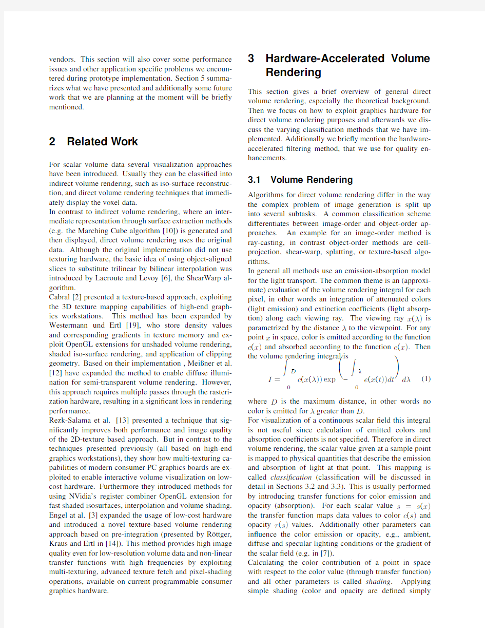
In general all methods use an emission-absorption model for the light transport.The common theme is an(approxi-mate)evaluation of the volume rendering integral for each pixel,in other words an integration of attenuated colors (light emission)and extinction coef?cients(light absorp-tion)along each viewing ray.The viewing ray x(λ)is parametrized by the distanceλto the viewpoint.For any point x in space,color is emitted according to the function c(x)and absorbed according to the function e(x).Then the volume rendering integral is
I=
D
c(x(λ))exp
?
λ
e(x(t))dt
dλ(1)
where D is the maximum distance,in other words no color is emitted forλgreater than D.
For visualization of a continuous scalar?eld this integral is not useful since calculation of emitted colors and absorption coef?cients is not speci?ed.Therefore in direct volume rendering,the scalar value given at a sample point is mapped to physical quantities that describe the emission and absorption of light at that point.This mapping is called classi?cation(classi?cation will be discussed in detail in Sections3.2and3.3).This is usually performed by introducing transfer functions for color emission and opacity(absorption).For each scalar value s=s(x) the transfer function maps data values to color c(s)and opacityτ(s)values.Additionally other parameters can in?uence the color emission or opacity, e.g.,ambient, diffuse and specular lighting conditions or the gradient of the scalar?eld(e.g.in[7]).
Calculating the color contribution of a point in space with respect to the color value(through transfer function) and all other parameters is called shading.Applying simple shading(color and opacity are de?ned simply
through classi?cation)the volume rendering integral can be written as
I=
D
0c(s(x(λ)))exp
?
λ
τ(s(x(t)))dt
dλ.(2)
Usually an analytical evaluation of the volume integral is not possible.Therefore usually a numerical approxima-tion of the integral is calculated using a Riemann sum for n equal ray segments of length d=D/n(see Section IV.A in[11]).This technique results in the common approxima-tion of the volume rendering integral
I≈
n
i=0
αi C i
i?1
j=0
(1?αj)(3)
which can be adapted for back-to-front compositing result-ing in the following equation
C i=αi C i+(1?αi)C i+1(4) where nowαi C i corresponds to c(s(x))from the volume rendering integral.The pre-multiplied colorαC is also called associated color([1]).
Due to the fact that a discrete approximation of the vol-ume rendering integral is performed,according to the sam-pling theorem,a correct reconstruction is only possible with sampling rates larger than the Nyquist frequency.Be-cause of the non-linearity of transfer functions(increases Nyquist frequency for the sampling),it is not suf?cient to sample a volume with the Nyquist frequency of the scalar?eld.This undersampling results in visual artifacts that can only be avoided by very smooth transfer func-tions.Section3.3gives a brief overview on a classi?ca-tion method realizing an improved approximation of the volume rendering.
3.2Pre-and Post-Classi?cation
As mentioned in the previous section classi?cation has an important part in direct volume rendering.Thus there are different techniques to perform the computation of c(s(x)) andτ(s(x)).In fact,volume data is presented by a3D array of sample points.According to sampling theory,a continuous signal can be reconstructed from these sam-pling points by convolution with an appropriate?lter ker-nel.The order of the reconstruction and the application of the transfer function de?nes the difference between pre-and post-classi?cation,which leads to remarkable differ-ent visual results.
Pre-classi?cation denotes the application of the transfer function to the discrete sample points before the data in-terpolation step.In other words the color and absorption are calculated in a pre-processing step for each sampling point and then used to interpolate c(s(x))andτ(s(x))for the computation of the volume rendering integral.
On the other side post-classi?cation reverses the order of operations.This type of classi?cation is characterized
by Figure1:Direct volume rendering without illumina-tion,pre-classi?ed(left),post-classi?ed(middle)and pre-integrated(right)
the application of the transfer function after the interpola-tion of s(x)from the scalar values of the discrete sampling points.With respect to the graphics pipeline the advantage of pre-classi?cation is,that an ef?cient implementation of this concept is possible on almost every graphics hard-ware.However the results achieved by this approach are not very convincing.Post-classi?cation is usually more complex to implement but achieves superior image qual-ity.The results of both pre-and post-classi?cation can be compared in Figure1.
3.3Pre-Integrated Classi?cation
As discussed at the end of Section3.1to gather better vi-sual results,the approximation of the volume rendering integral has to be improved.R¨o ttger et al.[14]used a pre-integrated classi?cation method to enhance cell-based volume reconstruction.This algorithm has been adapted for hardware accelerated direct volume rendering by En-gel et al.[3].The main idea of pre-integrated classi?ca-tion is to split the numerical integration process.Separate integration of the continuous scalar?eld and the transfer functions is performed to cope with the problematic of the Nyquist frequency.
In more detail,for each linear segment one table lookup is executed,where each segment is de?ned by the scalar value at the start of the segment s f,the scalar value at the end of the segment s b and the length of the segment d.The opacityαi of the i-th line segment is approximated by αi=1?exp
?
(i+1)d
id
τ(s(x(λ)))dλ
≈1?exp
?
1
τ((1?ω)s f+ωs b)d dω
.(5)
Analogously the associated color?Cτi(based on a non-associated color transfer function)is computed through
?Cτ
i
≈
1
τ((1?ω)s f+ωs b)c((1?ω)s f+ωs b)(6)×exp
?
ω
τ((1?ω )s f+ω s b)d dω
d dω.
Figure2:Alignment of texture slices for3D texturing on the left,and2D texturing on the right(image from Rezk-Salama et al.[13])
Both functions are dependent on s f,s b,and d(only if lengths of the segments are not equal).As usual the vol-ume rendering integral is approximated by evaluation of Equation(3).Because pre-integrated classi?cation always computes associated colors,αi C i in Equation(3)has to be substituted by?Cτi.
Through this principle the sampling rate does not depend anymore on the non-linearity of transfer functions,re-sulting in less undersampling artifacts.Therefore,pre-integrated classi?cation has two advantages,?rst it im-proves the accuracy of the visual results,and second fewer samples are required to achieve equal results regarding to the other presented classi?cation methods.
The major drawback of this approach is that the lookup ta-bles must be recomputed every time the transfer function changes.That strongly limits the interactivity of appli-cations employing this classi?cation approach.Therefore, the pre-integration step should be very fast.Engel et al.[3] proposes to assume a constant length of the segments,thus the dimensionality of the lookup table is reduced to two. By employing integral functions forτ(s)andτ(s)c(s)the evaluation of the integrals in Equations(5)and(6)can be greatly accelerated.Adapting this idea results in the following approximation of the opacity and the associated color
α(s f,s b,d)≈1?exp
?
d
s b?s f
(T(s b)?T(s f))
?Cτ(s
f ,s b,d)≈
d
s b?s f
(Kτ(s b)?Kτ(s f))(7)
with the integral functions T(s)= s
τ(s)ds and
Kτ(s)= s
τ(s)c(s)ds.This precalculation can eas-
ily performed since scalar values s are usually discrete. Thus,the numerical computing for producing the lookup tables can be minimized by only calculating the integral functions T(s)and Kτ(s).Afterwards computing the colors and opacities according to Equations(7)can be done without any further integration.This pre-calculation can be done in very short time,so providing interactivity in transfer-functions changes.The quality enhancement of pre-integrated classi?cation in comparison to pre-and post-classi?cation can be seen in Figure1.
How the presented classi?cation methods can be adapted for hardware-based volume rendering will be discussed in Section4.3.4Texture Based Volume Rendering Basically there are two different approaches how hardware acceleration can be used to perform volume rendering.
3D texture-mapped volume rendering
If3D-textures are supported by the hardware it is possible to download the whole volume data set as one single three-dimensional texture to hardware.Because hardware capable of3D-texturing is able to perform trilinear interpolation within the volume,it is possible to render a stack of polygon slices parallel to the image plane with respect to the current viewing direction(see Figure2,left).
This viewport-aligned slice stack has to be recomputed every time,the viewing position changes.Finally,in the compositing step,the textured polygons are blended onto the image-plane in a back-to-front order.This is done by using the alpha-blending capability of computer graphics hardware which usually results in a semitransparent view of the volume.Since slice polygons can be positioned arbitrarily,as many slices as required can be rendered, resulting in an image enhancement.However,in order to obtain equivalent representations while changing the number of slices,opacity values have to be adapted according to the slice distance.But rendering too many polygons results in even worse visualizations showing severe artifacts,because the frame buffer precision limits the number of slices,that can improve image quality further.
Since it is nearly a standard that3D texture mapping capabilities are now available on consumer-oriented graphics adapters(like the ATI-Radeon family[15]or the NVIDIA GeForce3and4[17])this approach is suitable for hardware accelerated volume rending on standard PC-platforms.
2D texture-mapped volume rendering
If hardware does not support3D texturing,2D texture mapping capabilities can be used for volume rendering. In this case,the polygon slices are set orthogonal to the principal viewing axes of the rectilinear data grid. Therefore if the the viewing direction changes by more than90degrees,the orientation of the slice normal has to be changed.This requires that the volume has to be represented through three stacks of slices,one for each slicing direction respectively,so the slice direction is object-aligned(see Figure2,right).
2D texturing hardware does not have the ability to perform trilinear interpolation.Because of that the slice polygons cannot be positioned arbitrarily within the volume.So the alignment of the slices with respect to the viewport is not possible.The trilinear interpolation(as performed by3D texturing hardware)is substituted by bilinear interpolation within each slice,which is although supported by hard-
ware.This results in strong visual artifacts due to the fact of the missing spatial interpolation.Another major draw-back of this approach in contrast to the previous one is the high memory requirements,because3instances of the volume data set have to be hold in memory.As in the3D texturing approach,to obtain equivalent representations, the opacity values have to be adopted.But now according to the slice distance between adjacent slices in direction of the viewing ray.
To enhance the image quality of2D texture based volume rendering,multitexturing capabilities can be used.To avoid the artifacts caused by the lack of spatial interpola-tion Rezk-Salama at al.[13]has introduced an approach to produce intermediate slices on the?y.To enable real trilinear interpolation the missing third interpolation step is performed within the rasterization hardware.Two?xed adjacent textured slices are combined using a component-wise weighted sum,exploiting the register combiners OpenGL extension by NVIDIA(see Section4).Thus linear interpolation between neighboring slices that are bilinearly?ltered in themselves produces again trilinear interpolation.A closer look on the implementation of these approaches is covered by Section4.1.
3.5High-Quality Filtering
Commodity graphics hardware can also be exploited to achieve hardware-accelerated high-quality?ltering with arbitrary?lter kernels,as introduced by Hadwiger et al.
[5].In this approach?ltering of input data is done by con-volving it with an arbitrary?lter kernel stored in multiple texture maps.As usual,the base is the evaluation of the well-known?lter convolution sum
g(x)=(f?h)(x)=
x +m
i= x ?m+1
f[i]h(x?i)(8)
this equation describes a convolution of the discrete in-put samples f[i]with a reconstruction?ler h(x)of(?nite) half-width m.
To be able to exploit standard graphics hardware to per-form this computation,the standard evaluation order(as used in software-based?ltering)has to be reordered.In-stead of gathering all input sample contributions within the kernel width neighborhood of a single input sample,this method distributes all single input sample contributions to all relevant output samples.The input sample function is stored in a single texture and the?lter kernel in multiple textures.Kernel textures are scaled to cover exactly the contributing samples.The number of contributing sam-ples is equal to the kernel width.To be able to perform the same operation for all samples at one time,the kernel has to be divided into several parts,to cover always only one input sample width.Such parts are called?lter tiles. Instead of imagining the?lter kernel being centered at the ”current”output sample location,an identical mapping of input samples to?lter values can be achieved by replicat-ing a single?lter tile mirrored in all dimensions repeatedly over the output sample grid.The scale of this mapping is chosen,so that the size of a single tile corresponds to the width from one input sample to the next.
The calculation of the contribution of a single speci?c?l-ter tile to all output samples is done in a single rendering pass.So the number of passes necessary is equal to the number of?lter tiles the?lter kernel used consists of.Due to the fact that only a single?lter tile is needed during a single rendering pass,all tiles are stored and downloaded to the graphics hardware as separate textures.If a given hardware architecture is able to support2n textures at the same time,the number of passes can be reduced by n. This method can be applied for volume rendering purposes by switching between two rendering contexts.One for the ?ltering and one for the rendering algorithm,whereas?rst a textured slice is?ltered according to the just described method,and afterwards the?ltered output is then used in the standard volume rendering pipeline.This is not as easy as it sounds,thus implementation dif?culties are described in more detail in section4.2.For results see Figure
3. Figure3:Pre-integrated classi?cation without pre-?ltered slices(left)and applying hardware-accelerated?ltering (right).
4Implementation
Our current implementation is based on a graphical user interface programmed in java,and a rendering library written in c++.For proper usage of the c++library in java, e.g for parameter passing,we exploit the functionality of the java native interface[16],which describes how to integrate native code within programs written in java. Due to the fact that our implementation is based on the OpenGL API[18],we need a library that maps the whole functionality of the native OpenGL library of the underlying operating system to java.Therefore we use the GL4Java library[4].The following detailed implementa-tion description will only cover the structure of the c++ rendering library,because all rendering functionality is encapsulated there.
On startup of the framework,the graphics adapter cur-
rently installed in the system is detected automatically. Regarding to the OpenGL extensions that are supported by the actual hardware the rendering modes that are not possible are disabled.Through this procedure,the framework is able to support a lot of different types of graphics adapters without changing the implementation. Anyway the framework is primarily based on graphics chips from NVidia and from ATI,because the OpenGL-extensions provided by these two vendors are very powerful features,which can be exploited very well for diverse direct volume rendering techniques.Minimum requirements for our application are multi-texturing capabilities.Full functionality includes the exploitation of the so called texture shader OpenGL extension and the register combiners provided by NVidia as well as the fragment shader extension,provided by ATI.
Basically the texture based volume rendering process can be split up into several principal subtasks.Each of these tasks is realized in one or more modules,to provide easy reuse possibilities.Therefore the implementation of new algorithms and the support of new hardware-features (OpenGL-extensions)is very simple by only extending these modules with additional functionality.The overall rendering implementation need to be changed to achieve support of new techniques or new graphics chips. Texture de?nition
As described in section 3.4,in the beginning of the rendering process the scalar volume data must be down-loaded to the hardware.According to the selected rendering mode,this is either be done as one single three-dimensional texture or as three stacks of two-dimensional textures.
The selected rendering mode additionally speci?es the texture format.In our context texture format means, what values are presented in a texture.Normally,RGBA (Red,green,blue and alpha component)color values are stored in a texture,but in volume rendering,other information as the volume gradient or the density value have to be accessed during the rasterization stage.For gradient vector reconstruction,we have implemented a central-difference?lter and additionally a sobel-operator, which results in a great quality enhancement in contrast to the central-difference method,avoiding severe shading artifacts(see Figure4).
When performing shading calculations,RGBA textures are usually employed,that contain the volume gradient in the RGB components and the volume scalar in the ALPHA component.As in pre-integrated rendering modes the scalar data has to be available in the?rst three components of the color vector,it is stored in the RED component.The?rst gradient component is stored in the ALPHA component in return.Another exception occurs for rendering modes,which are based on gradient-weighted opacity scaling,where the gradient magnitude is stored in the ALPHA component.Through the limitation of only four available color components, it is trivial that for the combination of some rendering modes it is not possible to store all the required values for a single slice in only one
texture.
Figure4:Gradient reconstruction using a central-difference?lter(left)and avoiding the shading artifacts (black holes)by using a sobel-operator(right) Projection
The geometry used for direct volume rendering,in contrast to other methods,e.g.iso-surface extraction,is usually very simple.Due to the fact that texture-based volume rendering algorithms usually perform slicing through a volume,the geometry only consists of a small number of primitives,one quadrilateral polygon for each slice,respectively.To obtain correct volume information for each slice,each polygon has to be bound to the corresponding textures that are required for the actual rendering mode.In addition,the texture coordinates have to be calculated https://www.sodocs.net/doc/9b6027389.html,ually this is a very simple task.
Just for2D-texture based pre-integrated classi?cation modes,it is a little bit more complex.Instead of the general slice-by-slice approach,this algorithm renders slab-by-slab(see Figure5)from back to front into the frame buffer.A single polygon is rendered for each slab with the front and the back texture as texture maps.To have texels along all viewing rays projected upon each other for the texel fetch operation,the back slice must be projected onto the front slice.This projection is per-formed by adapting texture coordinates for the projected texture slice,which always depends on the actual viewing transformation.
Compositing
Usually in hardware accelerated direct volume ren-dering approaches,the approximation of the volume rendering integral is done by back-to-front compositing of the rendered quadriliteral polygon slices.This should be performed according to Equation(4).In general this is achieved by blending the slices into the frame
Figure5:A slab of the volume between two slices.The scalar values on the front and on the back slice for a par-ticular viewing ray are called s f and s b(image from Engel et al.[3])
buffer with the OpenGL blending function glBlend-Func(GL ONE,GL ONE MINUS SRC ALPHA).
This is a correct evaluation only,if the color-values computed by the rasterization stage are associated colors.If they are not pre-multiplied(e.g.gradient-weighted opacity modes produce non-associated colors),then the blending function must be glBlend-Func(GL SRC ALPHA,GL ONE MINUS SRC ALPHA).
Iso-surface reconstruction in hardware is in general accomplished by storing the intensity value in the alpha-component of the fragment’s color.The volume is then rendered into the frame buffer using the OpenGL alpha-test to display the speci?ed isovalues only.
These two techniques can be combined for rendering semi-transparent iso-surfaces(see Figure6,left),where the alpha-test is used for rejecting all fragments not belonging to an iso-surface,and afterwards the slices are blended into the frame buffer,as described above. All fragments not belonging to an iso-surface are as-signed a special alpha-value of zero and the alpha test is then con?gured with the OpenGL function glAlpha-Func(GL GREATER,0.0),letting pass each fragment with an alpha value greater then zero.
Register settings
Depending on the selected rendering mode,during the rasterization process,the actual performed rendering technique often needs more input data than available through the slice textures(in general hold gradient and/or density information).For shading calculations the direc-tion of the light source must be known.When modelling specular re?ection the rasterization stage requires not only the light direction,but also the direction to the viewer’s eye,because a halfway vector is used to approximate the intensity of specular re?ection.Additionally some rendering modes need to access speci?c constant vectors, to perform dot-products for gradient reconstruction for example.This information has to be stored at a proper place.Therefore NVidia and ATI provide some special registers which can be accessed during rasterization process when using the register combiners extension or the fragment shader extension.
The register combiners extension,as described in[13],is able to access two constant color registers(in addition to the primary and secondary color),which is not suf?cient for complex rendering algorithms.In the GeForce3 graphics chip,NVidia has extended the register han-dling by introducing the register combiners2extension, providing per-combiner constant color registers.This means that each combiner-stage has access to its own two constant registers,so the maximum number of additional information,provided by RGBA vectors,is the number of combiner stages multiplied by two,respectively sixteen on GeForce3.In contrast all ATI graphics chips(e.g. Radeon8500,...),that support the OpenGL fragment shader extension provide access to an equal number of constant registers,namely eight.
Due to the fact that miscellaneous rendering modes need different information contained in the constant registers, the process of packing the required data into the correct registers is more complex than it sounds.In addition these constant settings intensely in?uence the programming of the rasterization stage,where each different register setting requires a new implementation of the rasterization process.
4.1NVIDIA vs.ATI
As mentioned above our current implementation supports several graphics chips from NVidia as well as several graphics chips from ATI.In this section we discuss the differences between realizations of several rendering algorithms according to the hardware-features supported by NVidia and ATI.The main focus is set on the pro-gramming of the?exible rasterization hardware,enabling advanced rendering techniques like per pixel-lighting or advanced texture-fetch methods.The differences will be discussed in detail by showing some implementation details for some concrete rendering modes after giving an short overview of rasterization hardware differences in OpenGL.
In general the?exible rasterization hardware consists of multi-texturing capabilities(allowing one polygon to be textured with image information obtained from multiple textures),multi-stage rasterization(allowing to explicitly control how color-,opacity-and texture-components are combined to form the resulting fragment,per-pixel shading)and dependent texture address modi?cation (allowing to perform diverse mathematical operations on texture coordinates and to use these results for another texture lookup).
NVidia
On graphics hardware with an NVidia chip,this ?exibility is provided through several OpenGL ex-tensions,mainly GL REGISTER COMBINERS NV and GL TEXTURE SHADER NV.When the register combiners extension is enabled,the standard OpenGL texturing units are completely bypassed and substituted by a register-based rasterization unit.This unit consists of two (eight on GeForce3,4)general combiner stages and one ?nal combiner stage.
Per-fragment information is stored in a set of input registers,and these can be combined,i.e.by dot product or component-wise weighted sum,the results are scaled and biased and?nally written to arbitrary output registers. The output registers of the?rst combiner stage are then input registers for the next stage,and so on.
When the per-stage-constants extension is enabled (GL PER STAGE CONSTANTS NV),for each combiner stage two additional registers are available,that can hold arbitrary data,otherwise two additional registers are available too,but with equal contents for every stage. The texture shader extension provides a superset of conventional OpenGL texture addressing.It provides a number of operations that can be used to compute texture coordinates per-fragment rather than using simple interpolated per-vertex coordinates.The shader opera-tions include for example standard texture access modes, dependent texture lookup(using the result from a previous texture stage to affect the lookup of the current stages), dot product texture access(performing dot products from texture coordinates and a vector derived from a previous stage)and several special modes.
The implementation of these extensions results in a lot of code,because the stages have to be con?gured properly, and an assembler like programming is not provided.
ATI
On graphics hardware with an ATI Radeon chip, this?exibility is provided through one OpenGL extension, GL FRAGMENT SHADER ATI.Generally this extension is very similar to the the extensions described before,but encapsulates the whole functionality in a single extension. The fragment shader extension inserts a?exible per-pixel programming model into the graphics pipeline in place of the traditional multi-texture pipeline.It provides a very general means of expressing fragment color blending and dependent texture address modi?cation.
The programming model is a register-based model and the number of instructions,texture lookups,read/write registers and constants is queryable. E.g.on the ATI Radeon8500there are six texture fetch operations and eight instructions possible,both two times during one rendering pass,yielding maximum of sixteen instructions in
total.Figure6:Semi-transparent iso-surface rendering(left)and pre-integrated volume rendering(right)of different human head data sets.
One advantageous property of the model is a uni?ed in-struction set used throughout the shader.That is,the same instructions are provided when operating on address or color data.Additionally,this uni?ed approach simpli?es programming(in contrast to the above presented NVidia extensions),because only a single instruction set has to be used and the fragment shader can be programmed comparable to an assembler language.
This tremendously reduces the amount of produced code and therefore accelerates and simpli?es debugging.For these reasons and because up to six textures are supported by the multi-texturing environment,ATI graphics chips provide powerful hardware features to perform hardware-accelerated high-quality volume rendering.
Pre-and Post-classi?cation
As described in detail in Section3.2,pre-and post-classi?cation differ in the order of the reconstruction step and the application of the transfer function.
Since most NVidia graphics chips sup-port paletted textures(OpenGL extension GL SHARED TEXTURE PALETTE EXT),pre-classi?ed volume rendering is easy to implement.Paletted textures means that instead of RGBA or luminance,the internal format of a texture is an index to a color-palette,repre-senting the mapping of a scalar value to a color(de?ned by transfer-function).This lookup is performed before the texture fetch operation(before the interpolation),thus pre-classi?ed volume rendering is performed.Since there is no similar OpenGL-extension supported by ATI graph-ics chips,rendering modes,based on pre-classi?cation are not available on ATI hardware.
Post-classi?cation is available on graphics-chips from both vendors,in case that advanced texture-fetch possi-bilities are available.As described in the beginning of this section when using the texture-and fragment-shader, dependent texture lookups can be performed.This feature is exploited for post-classi?cation purposes.The transfer function is downloaded as a one-dimensional texture
Figure7:Register combiner setup for gradient reconstruc-tion and interpolation with interpolation values stored in alpha(image from Engel et al.[3])
and for each texel,fetched by the given per-fragment texture coordinates,the scalar value is used as a lookup coordinate into the dependent1D transfer-function texture.Thus post-classi?cation is available,because the scalar value obtained from the?rst texture fetch has been bi-or trilinearly?ltered,dependent on whether 2D or3D volume-data textures are employed,and the transfer-function is applied afterwards.
Pre-integration
As post-classi?cation,pre-integrated classi?cation can also be performed on graphics-chips from both vendors if texture shading is available.The pre-integrated transfer-function,since dependent on two scalar values (s f from the front and s b from the back slice,see Figure 5and Section3.3for details)is downloaded as a two-dimensional texture,containing pre-integrated values for each of the possible combinations of front and back scalar values.
For each fragment,texels of two adjacent slices along each ray through the volume are projected onto each other. Then the two fetched texels are used as texture coordinates for a dependent texture lookup into the2D pre-integration texture.To extract the scalar values,usually stored in the red component of the texture,the dot product with a constant vector v=(1,0,0)T is applied.These values are then used for the lookup.
Pre-integrated volume rendering can also be employed to render multiple isosurfaces.The basic idea is to color each ray segment according to the?rst isosurface intersected by the ray segment.So the dependent texture contains color,transparency,and interpolation values (IP=(s iso?s f)/(s b?s f))for each combination of back and front scalar.For lighting purposes the gradient of the front and back slice has to be rebuilt in the RGB components and the two gradients have to be interpolated depending on the given isovalue.The implementation of this reconstruction using register combiners is shown in Figure7.
4.2Problems
As mentioned in the previous sections,the integration of different rendering techniques in one framework support-ing varying graphics chips requires a lot of care when im-plementing the varying methods.In addition to that im-plementation dif?culties,we encountered other problems as well.
When applying the hardware accelerated high quality?l-tering method(see Section3.5)in combination with an arbitrary rendering mode,we have to cope with different rendering contexts.One context for the rendering algo-rithm and one for the high quality?ltering.A single slice is rendered into a buffer,this result is then used in the?l-tering context to apply the speci?ed?ltering method(e.g. bi-cubic),and this result is then moved back into the ren-dering context,to perform i.e.the compositing step.More dif?cult is the case of combining the?ltering with preinte-gration,where two slices have to be switched between the rendering contexts.Through different contexts the geom-etry and the OpenGL state handling is varying depending on whether?ltering is applied or not.It is a challenge to de?ne and provide the correct data in the right context and not mixing up the complex state handling.Although the performance is not so high,the resulting visualizations are very convincing(see Figure1).
Another problem that occurs when realizing such a large framework is that the performance that usually is achieved by the varying algorithms can not be guaranteed.Further-more when performing shading,rendering datasets with dimensions over2563results in a heavy performance loss, caused by the memory bottle neck.Which means that not the whole data set can be downloaded to the graph-ics adapter memory,instead of,the textures are transferred between the main and the graphics memory.
5Conclusions and Future Work On the basis of standard2D-and3D-texture based vol-ume rendering and several high quality rendering tech-niques,we have presented a?exible framework,which in-tegrates several different direct volume rendering and iso-surface reconstruction techniques that exploit rasterization hardware of PC graphics boards in order to signi?cantly improve both performance and image quality.Addition-ally the framework can easily be extended with respect to support of new OpenGL extensions and implementa-tion of new rendering algorithms,by only expanding the proper modules.The framework supports most current low-cost graphics hardware and provides comparison pos-
sibilities for several hardware-accelerated volume visual-izations with regard to performance and quality.
In the future we plan the integration of non-photorealistic rendering techniques to enhance actual volume visual-izations as well as support of upcoming new graphics adapters.To overcome the problem that different graph-ics chips require different implementations,we will try the usage of a high-level shading language.
6Acknowledgements
This work was carried out as part of the basic research on visualization(http://www.VRVis.at/vis)at the VRVis Research Center Vienna,Austria(http://www.VRVis.at/), which is funded by an Austrian governmental research project called Kplus.
References
[1]James F.Blinn.Jim Blinn’s corner:Compositing.1.
Theory.IEEE Computer Graphics and Applications, 14(5):83–87,September1994.
[2]Brian Cabral,Nancy Cam,and Jim Foran.Acceler-
ated volume rendering and tomographic reconstruc-tion using texture mapping hardware.In1994Sym-posium on Volume Visualization,pages91–98.ACM SIGGRAPH,October1994.
[3]Klaus Engel,Martin Kraus,and Thomas Ertl.
High-quality pre-integrated volume rendering using hardware-accelerated pixel shading.In Proceedings of the ACM SIGGRAPH/EUROGRAPHICS work-shop on on Graphics hardware,pages9–16.ACM Press,2001.
[4]Jausoft OpenGL for Java web page.
https://www.sodocs.net/doc/9b6027389.html,/gl4java.html/.
[5]Markus Hadwiger,Thomas Theu?l,Helwig Hauser,
and Eduard Gr¨o ller.Hardware-accelerated high-quality reconstruction on PC hardware.In Pro-ceedings of the Vision Modeling and Visualization Conference2001(VMV-01),pages105–112,Berlin, November21–232001.Aka GmbH.
[6]Philippe Lacroute and Marc Levoy.Fast volume ren-
dering using a shear-warp factorization of the view-ing https://www.sodocs.net/doc/9b6027389.html,puter Graphics,28(Annual Conference Series):451–458,July1994.
[7]Marc Levoy.Display of surfaces from volume
data.IEEE Computer Graphics and Applications, 8(3):29–37,May1988.See corrigendum[9,20]. [8]Marc Levoy.Ef?cient ray tracing of volume data.
ACM Transactions on Graphics,9(3):245–261,July 1990.
[9]Marc Levoy.Letter to the editor:Error in volume
rendering paper was in exposition only.IEEE Com-puter Graphics and Applications,20(4):6–6,July/ August2000.
[10]William E.Lorensen and Harvey E.Cline.March-
ing cubes:A high resolution3D surface construction https://www.sodocs.net/doc/9b6027389.html,puter Graphics,21(4):163–169,July 1987.
[11]Nelson Max.Optical models for direct volume ren-
dering.IEEE Transactions on Visualization and Computer Graphics,1(2):99–108,June1995.ISSN 1077-2626.
[12]Michael Mei?ner,Ulrich Hoffmann,and Wolfgang
Stra?er.Enabling classi?cation and shading for 3D texture mapping based volume rendering using openGL and extensions.In IEEE Visualization’99, pages207–214,San Francisco,1999.IEEE. [13]C.Rezk-Salama,K.Engel,M.Bauer,G.Greiner,
and T.Ertl.Interactive volume rendering on stan-dard PC graphics hardware using multi-textures and multi-stage rasterization.pages109–118.
[14]Stefan R¨o ttger,Martin Kraus,and Thomas Ertl.
Hardware-accelerated volume and isosurface render-ing based on cell-projection.pages109–116.IEEE Computer Society Technical Committee on Com-puter Graphics,2000.
[15]ATI web page.https://www.sodocs.net/doc/9b6027389.html,/.
[16]JA V A web page.https://www.sodocs.net/doc/9b6027389.html,/.
[17]NVIDIA web page.https://www.sodocs.net/doc/9b6027389.html,/.
[18]OpenGL web page.https://www.sodocs.net/doc/9b6027389.html,/.
[19]R¨u diger Westermann and Thomas Ertl.Ef?ciently
using graphics hardware in volume rendering appli-cations.In SIGGRAPH98Conference Proceedings, Annual Conference Series,pages169–178.ACM SIGGRAPH,Addison Wesley,July1998.
[20]Craig Wittenbrink,Tom Malzbender,and Mike Goss.
Letter to the editor:Interpolation for volume ren-dering.IEEE Computer Graphics and Applications, 20(5):6–6,September/October2000.See[7,9].
公文写作规范格式
商务公文写作目录 一、商务公文的基本知识 二、应把握的事项与原则 三、常用商务公文写作要点 四、常见错误与问题
一、商务公文的基本知识 1、商务公文的概念与意义 商务公文是商业事务中的公务文书,是企业在生产经营管理活动中产生的,按照严格的、既定的生效程序和规范的格式而制定的具有传递信息和记录作用的载体。规范严谨的商务文书,不仅是贯彻企业执行力的重要保障,而且已经成为现代企业管理的基础中不可或缺的内容。商务公文的水平也是反映企业形象的一个窗口,商务公文的写作能力常成为评价员工职业素质的重要尺度之一。 2、商务公文分类:(1)根据形成和作用的商务活动领域,可分为通用公文和专用公文两类(2)根据内容涉及秘密的程度,可分为对外公开、限国内公开、内部使用、秘密、机密、绝密六类(3)根据行文方向,可分为上行文、下行文、平行文三类(4)根据内容的性质,可分为规范性、指导性、公布性、陈述呈请性、商洽性、证明性公文(5)根据处理时限的要求,可分为平件、急件、特急件三类(6)根据来源,在一个部门内部可分为收文、发文两类。 3、常用商务公文: (1)公务信息:包括通知、通报、通告、会议纪要、会议记录等 (2)上下沟通:包括请示、报告、公函、批复、意见等 (3)建规立矩:包括企业各类管理规章制度、决定、命令、任命等; (4)包容大事小情:包括简报、调查报告、计划、总结、述职报告等; (5)对外宣传:礼仪类应用文、领导演讲稿、邀请函等; (6)财经类:经济合同、委托授权书等; (7)其他:电子邮件、便条、单据类(借条、欠条、领条、收条)等。 考虑到在座的主要岗位,本次讲座涉及请示、报告、函、计划、总结、规章制度的写作,重点谈述职报告的写作。 4、商务公文的特点: (1)制作者是商务组织。(2)具有特定效力,用于处理商务。 (3)具有规范的结构和格式,而不像私人文件靠“约定俗成”的格式。商务公文区别于其它文章的主要特点是具有法定效力与规范格式的文件。 5、商务公文的四个构成要素: (1)意图:主观上要达到的目标 (2)结构:有效划分层次和段落,巧设过渡和照应 (3)材料:组织材料要注意多、细、精、严 (4) 正确使用专业术语、熟语、流行语等词语,适当运用模糊语言、模态词语与古词语。 6、基本文体与结构 商务文体区别于其他文体的特殊属性主要有直接应用性、全面真实性、结构格式的规范性。其特征表现为:被强制性规定采用白话文形式,兼用议论、说明、叙述三种基本表达方法。商务公文的基本组成部分有:标题、正文、作者、日期、印章或签署、主题词。其它组成部分有文头、发文字号、签发人、保密等级、紧急程度、主送机关、附件及其标记、抄送机关、注释、印发说明等。印章或签署均为证实公文作者合法性、真实性及公文效力的标志。 7、稿本 (1)草稿。常有“讨论稿”“征求意见稿”“送审稿”“草稿”“初稿”“二稿”“三稿”等标记。(2)定稿。是制作公文正本的标准依据。有法定的生效标志(签发等)。(3)正本。格式正规并有印章或签署等表明真实性、权威性、有效性。(4)试行本。在试验期间具有正式公文的法定效力。(5)暂行本。在规定
关于会议纪要的规范格式和写作要求
关于会议纪要的规范格式和写作要求 一、会议纪要的概念 会议纪要是一种记载和传达会议基本情况或主要精神、议定事项等内容的规定性公文。是在会议记录的基础上,对会议的主要内容及议定的事项,经过摘要整理的、需要贯彻执行或公布于报刊的具有纪实性和指导性的文件。 会议纪要根据适用范围、内容和作用,分为三种类型: 1、办公会议纪要(也指日常行政工作类会议纪要),主要用于单位开会讨论研究问题,商定决议事项,安排布置工作,为开展工作提供指导和依据。如,xx学校工作会议纪要、部长办公会议纪要、市委常委会议纪要。 2、专项会议纪要(也指协商交流性会议纪要),主要用于各类交流会、研讨会、座谈会等会议纪要,目的是听取情况、传递信息、研讨问题、启发工作等。如,xx县脱贫致富工作座谈会议纪要。 3、代表会议纪要(也指程序类会议纪要)。它侧重于记录会议议程和通过的决议,以及今后工作的建议。如《××省第一次盲人聋哑人代表会议纪要》、《xx市第x次代表大会会议纪要》。 另外,还有工作汇报、交流会,部门之间的联席会等方面的纪要,但基本上都系日常工作类的会议纪要。 二、会议纪要的格式 会议纪要通常由标题、正文、结尾三部分构成。
1、标题有三种方式:一是会议名称加纪要,如《全国农村工作会议纪要》;二是召开会议的机关加内容加纪要,也可简化为机关加纪要,如《省经贸委关于企业扭亏会议纪要》、《xx组织部部长办公会议纪要》;三是正副标题相结合,如《维护财政制度加强经济管理——在xx部门xx座谈会上的发言纪要》。 会议纪要应在标题的下方标注成文日期,位置居中,并用括号括起。作为文件下发的会议纪要应在版头部分标注文号,行文单位和成文日期在文末落款(加盖印章)。 2、会议纪要正文一般由两部分组成。 (1)开头,主要指会议概况,包括会议时间、地点、名称、主持人,与会人员,基本议程。 (2)主体,主要指会议的精神和议定事项。常务会、办公会、日常工作例会的纪要,一般包括会议内容、议定事项,有的还可概述议定事项的意义。工作会议、专业会议和座谈会的纪要,往往还要写出经验、做法、今后工作的意见、措施和要求。 (3)结尾,主要是对会议的总结、发言评价和主持人的要求或发出的号召、提出的要求等。一般会议纪要不需要写结束语,主体部分写完就结束。 三、会议纪要的写法 根据会议性质、规模、议题等不同,正文部分大致可以有以下几种写法: 1、集中概述法(综合式)。这种写法是把会议的基本情况,讨
titlesec宏包使用手册
titlesec&titletoc中文文档 张海军编译 makeday1984@https://www.sodocs.net/doc/9b6027389.html, 2009年10月 目录 1简介,1 2titlesec基本功能,2 2.1.格式,2.—2.2.间隔, 3.—2.3.工具,3. 3titlesec用法进阶,3 3.1.标题格式,3.—3.2.标题间距, 4.—3.3.与间隔相关的工具, 5.—3.4.标题 填充,5.—3.5.页面类型,6.—3.6.断行,6. 4titletoc部分,6 4.1.titletoc快速上手,6. 1简介 The titlesec and titletoc宏包是用来改变L A T E X中默认标题和目录样式的,可以提供当前L A T E X中没有的功能。Piet van Oostrum写的fancyhdr宏包、Rowland McDonnell的sectsty宏包以及Peter Wilson的tocloft宏包用法更容易些;如果希望用法简单的朋友,可以考虑使用它们。 要想正确使用titlesec宏包,首先要明白L A T E X中标题的构成,一个完整的标题是由标签+间隔+标题内容构成的。比如: 1.这是一个标题,此标题中 1.就是这个标题的标签,这是一个标签是此标题的内容,它们之间的间距就是间隔了。 1
2titlesec基本功能 改变标题样式最容易的方法就是用几向个命令和一系列选项。如果你感觉用这种方法已经能满足你的需求,就不要读除本节之外的其它章节了1。 2.1格式 格式里用三组选项来控制字体的簇、大小以及对齐方法。没有必要设置每一个选项,因为有些选项已经有默认值了。 rm s f t t md b f up i t s l s c 用来控制字体的族和形状2,默认是bf,详情见表1。 项目意义备注(相当于) rm roman字体\textrm{...} sf sans serif字体\textsf{...} tt typewriter字体\texttt{...} md mdseries(中等粗体)\textmd{...} bf bfseries(粗体)\textbf{...} up直立字体\textup{...} it italic字体\textit{...} sl slanted字体\textsl{...} sc小号大写字母\textsc{...} 表1:字体族、形状选项 bf和md属于控制字体形状,其余均是切换字体族的。 b i g medium s m a l l t i n y(大、中、小、很小) 用来标题字体的大小,默认是big。 1这句话是宏包作者说的,不过我感觉大多情况下,是不能满足需要的,特别是中文排版,英文 可能会好些! 2L A T E X中的字体有5种属性:编码、族、形状、系列和尺寸。 2
毕业论文写作要求与格式规范
毕业论文写作要求与格式规范 关于《毕业论文写作要求与格式规范》,是我们特意为大家整理的,希望对大家有所帮助。 (一)文体 毕业论文文体类型一般分为:试验论文、专题论文、调查报告、文献综述、个案评述、计算设计等。学生根据自己的实际情况,可以选择适合的文体写作。 (二)文风 符合科研论文写作的基本要求:科学性、创造性、逻辑性、
实用性、可读性、规范性等。写作态度要严肃认真,论证主题应有一定理论或应用价值;立论应科学正确,论据应充实可靠,结构层次应清晰合理,推理论证应逻辑严密。行文应简练,文笔应通顺,文字应朴实,撰写应规范,要求使用科研论文特有的科学语言。 (三)论文结构与排列顺序 毕业论文,一般由封面、独创性声明及版权授权书、摘要、目录、正文、后记、参考文献、附录等部分组成并按前后顺序排列。 1.封面:毕业论文(设计)封面具体要求如下: (1)论文题目应能概括论文的主要内容,切题、简洁,不超过30字,可分两行排列;
(2)层次:大学本科、大学专科 (3)专业名称:机电一体化技术、计算机应用技术、计算机网络技术、数控技术、模具设计与制造、电子信息、电脑艺术设计、会计电算化、商务英语、市场营销、电子商务、生物技术应用、设施农业技术、园林工程技术、中草药栽培技术和畜牧兽医等专业,应按照标准表述填写; (4)日期:毕业论文(设计)完成时间。 2.独创性声明和关于论文使用授权的说明:需要学生本人签字。 3.摘要:论文摘要的字数一般为300字左右。摘要是对论文的内容不加注释和评论的简短陈述,是文章内容的高度概括。主要内容包括:该项研究工作的内容、目的及其重要性;所使用的实验方法;总结研究成果,突出作者的新见解;研究结论及其意义。摘要中不列举例证,不描述研究过程,不做自我评价。
公文格式规范与常见公文写作
公文格式规范与常见公文写作 一、公文概述与公文格式规范 党政机关公文种类的区分、用途的确定及格式规范等,由中共中央办公厅、国务院办公厅于2012年4月16日印发,2012年7月1日施行的《党政机关公文处理工作条例》规定。之前相关条例、办法停止执行。 (一)公文的含义 公文,即公务文书的简称,属应用文。 广义的公文,指党政机关、社会团体、企事业单位,为处理公务按照一定程序而形成的体式完整的文字材料。 狭义的公文,是指在机关、单位之间,以规范体式运行的文字材料,俗称“红头文件”。 ?(二)公文的行文方向和原则 ?、上行文下级机关向上级机关行文。有“请示”、“报告”、和“意见”。 ?、平行文同级机关或不相隶属机关之间行文。主要有“函”、“议案”和“意见”。 ?、下行文上级机关向下级机关行文。主要有“决议”、“决定”、“命令”、“公报”、“公告”、“通告”、“意见”、“通知”、“通报”、“批复”和“会议纪要”等。 ?其中,“意见”、“会议纪要”可上行文、平行文、下行文。?“通报”可下行文和平行文。 ?原则: ?、根据本机关隶属关系和职权范围确定行文关系 ?、一般不得越级行文 ?、同级机关可以联合行文 ?、受双重领导的机关应分清主送机关和抄送机关 ?、党政机关的部门一般不得向下级党政机关行文 ?(三) 公文的种类及用途 ?、决议。适用于会议讨论通过的重大决策事项。 ?、决定。适用于对重要事项作出决策和部署、奖惩有关单位和人员、变更或撤销下级机关不适当的决定事项。
?、命令(令)。适用于公布行政法规和规章、宣布施行重大强制性措施、批准授予和晋升衔级、嘉奖有关单位和人员。 ?、公报。适用于公布重要决定或者重大事项。 ?、公告。适用于向国内外宣布重要事项或者法定事项。 ?、通告。适用于在一定范围内公布应当遵守或者周知的事项。?、意见。适用于对重要问题提出见解和处理办法。 ?、通知。适用于发布、传达要求下级机关执行和有关单位周知或者执行的事项,批转、转发公文。 ?、通报。适用于表彰先进、批评错误、传达重要精神和告知重要情况。 ?、报告。适用于向上级机关汇报工作、反映情况,回复上级机关的询问。 ?、请示。适用于向上级机关请求指示、批准。 ?、批复。适用于答复下级机关请示事项。 ?、议案。适用于各级人民政府按照法律程序向同级人民代表大会或者人民代表大会常务委员会提请审议事项。 ?、函。适用于不相隶属机关之间商洽工作、询问和答复问题、请求批准和答复审批事项。 ?、纪要。适用于记载会议主要情况和议定事项。?(四)、公文的格式规范 ?、眉首的规范 ?()、份号 ?也称编号,置于公文首页左上角第行,顶格标注。“秘密”以上等级的党政机关公文,应当标注份号。 ?()、密级和保密期限 ?分“绝密”、“机密”、“秘密”三个等级。标注在份号下方。?()、紧急程度 ?分为“特急”和“加急”。由公文签发人根据实际需要确定使用与否。标注在密级下方。 ?()、发文机关标志(或称版头) ?由发文机关全称或规范化简称加“文件”二字组成。套红醒目,位于公文首页正中居上位置(按《党政机关公文格式》标准排
ctex 宏包说明 ctex
ctex宏包说明 https://www.sodocs.net/doc/9b6027389.html,? 版本号:v1.02c修改日期:2011/03/11 摘要 ctex宏包提供了一个统一的中文L A T E X文档框架,底层支持CCT、CJK和xeCJK 三种中文L A T E X系统。ctex宏包提供了编写中文L A T E X文档常用的一些宏定义和命令。 ctex宏包需要CCT系统或者CJK宏包或者xeCJK宏包的支持。主要文件包括ctexart.cls、ctexrep.cls、ctexbook.cls和ctex.sty、ctexcap.sty。 ctex宏包由https://www.sodocs.net/doc/9b6027389.html,制作并负责维护。 目录 1简介2 2使用帮助3 2.1使用CJK或xeCJK (3) 2.2使用CCT (3) 2.3选项 (4) 2.3.1只能用于文档类的选项 (4) 2.3.2只能用于文档类和ctexcap.sty的选项 (4) 2.3.3中文编码选项 (4) 2.3.4中文字库选项 (5) 2.3.5CCT引擎选项 (5) 2.3.6排版风格选项 (5) 2.3.7宏包兼容选项 (6) 2.3.8缺省选项 (6) 2.4基本命令 (6) 2.4.1字体设置 (6) 2.4.2字号、字距、字宽和缩进 (7) ?https://www.sodocs.net/doc/9b6027389.html, 1
1简介2 2.4.3中文数字转换 (7) 2.5高级设置 (8) 2.5.1章节标题设置 (9) 2.5.2部分修改标题格式 (12) 2.5.3附录标题设置 (12) 2.5.4其他标题设置 (13) 2.5.5其他设置 (13) 2.6配置文件 (14) 3版本更新15 4开发人员17 1简介 这个宏包的部分原始代码来自于由王磊编写cjkbook.cls文档类,还有一小部分原始代码来自于吴凌云编写的GB.cap文件。原来的这些工作都是零零碎碎编写的,没有认真、系统的设计,也没有用户文档,非常不利于维护和改进。2003年,吴凌云用doc和docstrip工具重新编写了整个文档,并增加了许多新的功能。2007年,oseen和王越在ctex宏包基础上增加了对UTF-8编码的支持,开发出了ctexutf8宏包。2009年5月,我们在Google Code建立了ctex-kit项目1,对ctex宏包及相关宏包和脚本进行了整合,并加入了对XeT E X的支持。该项目由https://www.sodocs.net/doc/9b6027389.html,社区的开发者共同维护,新版本号为v0.9。在开发新版本时,考虑到合作开发和调试的方便,我们不再使用doc和docstrip工具,改为直接编写宏包文件。 最初Knuth设计开发T E X的时候没有考虑到支持多国语言,特别是多字节的中日韩语言。这使得T E X以至后来的L A T E X对中文的支持一直不是很好。即使在CJK解决了中文字符处理的问题以后,中文用户使用L A T E X仍然要面对许多困难。最常见的就是中文化的标题。由于中文习惯和西方语言的不同,使得很难直接使用原有的标题结构来表示中文标题。因此需要对标准L A T E X宏包做较大的修改。此外,还有诸如中文字号的对应关系等等。ctex宏包正是尝试着解决这些问题。中间很多地方用到了在https://www.sodocs.net/doc/9b6027389.html,论坛上的讨论结果,在此对参与讨论的朋友们表示感谢。 ctex宏包由五个主要文件构成:ctexart.cls、ctexrep.cls、ctexbook.cls和ctex.sty、ctexcap.sty。ctex.sty主要是提供整合的中文环境,可以配合大多数文档类使用。而ctexcap.sty则是在ctex.sty的基础上对L A T E X的三个标准文档类的格式进行修改以符合中文习惯,该宏包只能配合这三个标准文档类使用。ctexart.cls、ctexrep.cls、ctexbook.cls则是ctex.sty、ctexcap.sty分别和三个标准文档类结合产生的新文档类,除了包含ctex.sty、ctexcap.sty的所有功能,还加入了一些修改文档类缺省设置的内容(如使用五号字体为缺省字体)。 1https://www.sodocs.net/doc/9b6027389.html,/p/ctex-kit/
文档书写格式规范要求
学生会文档书写格式规范要求 目前各部门在日常文书编撰中大多按照个人习惯进行排版,文档中字体、文字大小、行间距、段落编号、页边距、落款等参数设置不规范,严重影响到文书的标准性和美观性,以下是文书标准格式要求及日常文档书写注意事项,请各部门在今后工作中严格实行: 一、文件要求 1.文字类采用Word格式排版 2.统计表、一览表等表格统一用Excel格式排版 3.打印材料用纸一般采用国际标准A4型(210mm×297mm),左侧装订。版面方向以纵向为主,横向为辅,可根据实际需要确定 4.各部门的职责、制度、申请、请示等应一事一报,禁止一份行文内同时表述两件工作。 5.各类材料标题应规范书写,明确文件主要内容。 二、文件格式 (一)标题 1.文件标题:标题应由发文机关、发文事由、公文种类三部分组成,黑体小二号字,不加粗,居中,段后空1行。 (二)正文格式 1. 正文字体:四号宋体,在文档中插入表格,单元格内字体用宋体,字号可根据内容自行设定。 2.页边距:上下边距为2.54厘米;左右边距为 3.18厘米。
3.页眉、页脚:页眉为1.5厘米;页脚为1.75厘米; 4.行间距:1.5倍行距。 5.每段前的空格请不要使用空格,应该设置首先缩进2字符 6.年月日表示:全部采用阿拉伯数字表示。 7.文字从左至右横写。 (三)层次序号 (1)一级标题:一、二、三、 (2)二级标题:(一)(二)(三) (3)三级标题:1. 2. 3. (4)四级标题:(1)(2)(3) 注:三个级别的标题所用分隔符号不同,一级标题用顿号“、”例如:一、二、等。二级标题用括号不加顿号,例如:(三)(四)等。三级标题用字符圆点“.”例如:5. 6.等。 (四)、关于落款: 1.对外行文必须落款“湖南环境生物专业技术学院学生会”“校学生会”各部门不得随意使用。 2.各部门文件落款需注明组织名称及部门“湖南环境生物专业技术学院学生会XX部”“校学生会XX部” 3.所有行文落款不得出现“环境生物学院”“湘环学院”“学生会”等表述不全的简称。 4.落款填写至文档末尾右对齐,与前一段间隔2行 5.时间落款:文档中落款时间应以“2016年5月12日”阿拉伯数字
政府公文写作格式规范
政府公文写作格式 一、眉首部分 (一)发文机关标识 平行文和下行文的文件头,发文机关标识上边缘至上页边为62mm,发文机关下边缘至红色反线为28mm。 上行文中,发文机关标识上边缘至版心上边缘为80mm,即与上页边距离为117mm,发文机关下边缘至红色反线为30mm。 发文机关标识使用字体为方正小标宋_GBK,字号不大于22mm×15mm。 (二)份数序号 用阿拉伯数字顶格标识在版心左上角第一行,不能少于2位数。标识为“编号000001” (三)秘密等级和保密期限 用3号黑体字顶格标识在版心右上角第一行,两字中间空一字。如需要加保密期限的,密级与期限间用“★”隔开,密级中则不空字。 (四)紧急程度 用3号黑体字顶格标识在版心右上角第一行,两字中间空一字。如同时标识密级,则标识在右上角第二行。 (五)发文字号 标识在发文机关标识下两行,用3号方正仿宋_GBK字体剧
中排布。年份、序号用阿拉伯数字标识,年份用全称,用六角括号“〔〕”括入。序号不用虚位,不用“第”。发文字号距离红色反线4mm。 (六)签发人 上行文需要标识签发人,平行排列于发文字号右侧,发文字号居左空一字,签发人居右空一字。“签发人”用3号方正仿宋_GBK,后标全角冒号,冒号后用3号方正楷体_GBK标识签发人姓名。多个签发人的,主办单位签发人置于第一行,其他从第二行起排在主办单位签发人下,下移红色反线,最后一个签发人与发文字号在同一行。 二、主体部分 (一)标题 由“发文机关+事由+文种”组成,标识在红色反线下空两行,用2号方正小标宋_GBK,可一行或多行居中排布。 (二)主送机关 在标题下空一行,用3号方正仿宋_GBK字体顶格标识。回行是顶格,最后一个主送机关后面用全角冒号。 (三)正文 主送机关后一行开始,每段段首空两字,回行顶格。公文中的数字、年份用阿拉伯数字,不能回行,阿拉伯数字:用3号Times New Roman。正文用3号方正仿宋_GBK,小标题按照如下排版要求进行排版:
tabularx宏包中改变弹性列的宽度
tabularx宏包中改变弹性列的宽度\hsize 分类:latex 2012-03-07 21:54 12人阅读评论(0) 收藏编辑删除 \documentclass{article} \usepackage{amsmath} \usepackage{amssymb} \usepackage{latexsym} \usepackage{CJK} \usepackage{tabularx} \usepackage{array} \newcommand{\PreserveBackslash}[1]{\let \temp =\\#1 \let \\ = \temp} \newcolumntype{C}[1]{>{\PreserveBackslash\centering}p{#1}} \newcolumntype{R}[1]{>{\PreserveBackslash\raggedleft}p{#1}} \newcolumntype{L}[1]{>{\PreserveBackslash\raggedright}p{#1}} \begin{document} \begin{CJK*}{GBK}{song} \CJKtilde \begin{tabularx}{10.5cm}{|p{3cm} |>{\setlength{\hsize}{.5\hsize}\centering}X |>{\setlength{\hsize}{1.5\hsize}}X|} %\hsize是自动计算的列宽度,上面{.5\hsize}与{1.5\hsize}中的\hsize前的数字加起来必须等于表格的弹性列数量。对于本例,弹性列有2列,所以“.5+1.5=2”正确。 %共3列,总列宽为10.5cm。第1列列宽为3cm,第3列的列宽是第2列列宽的3倍,其宽度自动计算。第2列文字左右居中对齐。注意:\multicolum命令不能跨越X列。 \hline 聪明的鱼儿在咬钩前常常排祠再三& 这是因为它们要荆断食物是否安全&知果它们认为有危险\\ \hline 它们枕不会吃& 如果它们判定没有危险& 它们就食吞钩\\ \hline 一眼识破诱饵的危险,却又不由自主地去吞钩的& 那才正是人的心理而不是鱼的心理& 是人的愚合而不是鱼的恳奋\\
2-1论文写作要求与格式规范(2009年修订)
广州中医药大学研究生学位论文基本要求与写作规范 为了进一步提高学位工作水平和学位论文质量,保证我校学位论文在结构和格式上的规范与统一,特做如下规定: 一、学位论文基本要求 (一)科学学位硕士论文要求 1.论文的基本科学论点、结论,应在中医药学术上和中医药科学技术上具有一定的理论意义和实践价值。 2.论文所涉及的内容,应反映出作者具有坚实的基础理论和系统的专门知识。 3.实验设计和方法比较先进,并能掌握本研究课题的研究方法和技能。 4.对所研究的课题有新的见解。 5.在导师指导下研究生独立完成。 6.论文字数一般不少于3万字,中、英文摘要1000字左右。 (二)临床专业学位硕士论文要求 临床医学硕士专业学位申请者在临床科研能力训练中学会文献检索、收集资料、数据处理等科学研究的基本方法,培养临床思维能力与分析能力,完成学位论文。 1.学位论文包括病例分析报告及文献综述。 2.学位论文应紧密结合中医临床或中西结合临床实际,以总结临床实践经验为主。 3.学位论文应表明申请人已经掌握临床科学研究的基本方法。 4.论文字数一般不少于15000字,中、英文摘要1000字左右。 (三)科学学位博士论文要求 1.研究的课题应在中医药学术上具有较大的理论意义和实践价值。 2.论文所涉及的内容应反映作者具有坚实宽广的理论基础和系统深入的专门知识,并表明作者具有独立从事科学研究工作的能力。 3.实验设计和方法在国内同类研究中属先进水平,并能独立掌握本研究课题的研究方法和技能。
4.对本研究课题有创造性见解,并取得显著的科研成果。 5.学位论文必须是作者本人独立完成,与他人合作的只能提出本人完成的部分。 6.论文字数不少于5万字,中、英摘要3000字;详细中文摘要(单行本)1万字左右。 (四)临床专业学位博士论文要求 1.要求论文课题紧密结合中医临床或中西结合临床实际,研究结果对临床工作具有一定的应用价值。 2.论文表明研究生具有运用所学知识解决临床实际问题和从事临床科学研究的能力。 3.论文字数一般不少于3万字,中、英文摘要2000字;详细中文摘要(单行本)5000字左右。 二、学位论文的格式要求 (一)学位论文的组成 博士、硕士学位论文一般应由以下几部分组成,依次为:1.论文封面;2. 原创性声明及关于学位论文使用授权的声明;3.中文摘要;4.英文摘要;5.目录; 6.引言; 7.论文正文; 8.结语; 9.参考文献;10.附录;11.致谢。 1.论文封面:采用研究生处统一设计的封面。论文题目应以恰当、简明、引人注目的词语概括论文中最主要的内容。避免使用不常见的缩略词、缩写字,题名一般不超过30个汉字。论文封面“指导教师”栏只写入学当年招生简章注明、经正式遴选的指导教师1人,协助导师名字不得出现在论文封面。 2.原创性声明及关于学位论文使用授权的声明(后附)。 3.中文摘要:要说明研究工作目的、方法、成果和结论。并写出论文关键词3~5个。 4.英文摘要:应有题目、专业名称、研究生姓名和指导教师姓名,内容与中文提要一致,语句要通顺,语法正确。并列出与中文对应的论文关键词3~5个。 5.目录:将论文各组成部分(1~3级)标题依次列出,标题应简明扼要,逐项标明页码,目录各级标题对齐排。 6.引言:在论文正文之前,简要说明研究工作的目的、范围、相关领域前人所做的工作和研究空白,本研究理论基础、研究方法、预期结果和意义。应言简
公文写作毕业论文写作要求和格式规范
(公文写作)毕业论文写作要求和格式规范
中国农业大学继续教育学院 毕业论文写作要求和格式规范 壹、写作要求 (壹)文体 毕业论文文体类型壹般分为:试验论文、专题论文、调查方案、文献综述、个案评述、计算设计等。学生根据自己的实际情况,能够选择适合的文体写作。 (二)文风 符合科研论文写作的基本要求:科学性、创造性、逻辑性、实用性、可读性、规范性等。写作态度要严肃认真,论证主题应有壹定理论或应用价值;立论应科学正确,论据应充实可靠,结构层次应清晰合理,推理论证应逻辑严密。行文应简练,文笔应通顺,文字应朴实,撰写应规范,要求使用科研论文特有的科学语言。 (三)论文结构和排列顺序 毕业论文,壹般由封面、独创性声明及版权授权书、摘要、目录、正文、后记、参考文献、附录等部分组成且按前后顺序排列。 1.封面:毕业论文(设计)封面(见文件5)具体要求如下: (1)论文题目应能概括论文的主要内容,切题、简洁,不超过30字,可分俩行排列; (2)层次:高起本,专升本,高起专; (3)专业名称:现开设园林、农林经济管理、会计学、工商管理等专业,应按照标准表述填写; (4)密级:涉密论文注明相应保密年限; (5)日期:毕业论文完成时间。 2.独创性声明和关于论文使用授权的说明:(略)。
3.摘要:论文摘要的字数壹般为300字左右。摘要是对论文的内容不加注释和评论的简短陈述,是文章内容的高度概括。主要内容包括:该项研究工作的内容、目的及其重要性;所使用的实验方法;总结研究成果,突出作者的新见解;研究结论及其意义。摘要中不列举例证,不描述研究过程,不做自我评价。 论文摘要后另起壹行注明本文的关键词,关键词是供检索用的主题词条,应采用能够覆盖论文内容的通用专业术语,符合学科分类,壹般为3~5个,按照词条的外延层次从大到小排列。 4.目录(目录示例见附件3):独立成页,包括论文中的壹级、二级标题、后记、参考文献、和附录以及各项所于的页码。 5.正文:包括前言、论文主体和结论 前言:为正文第壹部分内容,简单介绍本项研究的背景和国内外研究成果、研究现状,明确研究目的、意义以及要解决的问题。 论文主体:是全文的核心部分,于正文中应将调查、研究中所得的材料和数据加工整理和分析研究,提出论点,突出创新。内容可根据学科特点和研究内容的性质而不同。壹般包括:理论分析、计算方法、实验装置和测试方法、对实验结果或调研结果的分析和讨论,本研究方法和已有研究方法的比较等方面。内容要求论点正确,推理严谨,数据可靠,文字精炼,条理分明,重点突出。 结论:为正文最后壹部分,是对主要成果的归纳和总结,要突出创新点,且以简练的文字对所做的主要工作进行评价。 6.后记:对整个毕业论文工作进行简单的回顾总结,对给予毕业论文工作提供帮助的组织或个人表示感谢。内容应尽量简单明了,壹般为200字左右。 7.参考文献:是论文不可或缺的组成部分。它既可反映毕业论文工作中取材广博程度,又可反映文稿的科学依据和作者尊重他人研究成果的严肃态度,仍能够向读者提供有关
配合前面的ntheorem宏包产生各种定理结构
%=== 配合前面的ntheorem宏包产生各种定理结构,重定义一些正文相关标题===% \theoremstyle{plain} \theoremheaderfont{\normalfont\rmfamily\CJKfamily{hei}} \theorembodyfont{\normalfont\rm\CJKfamily{song}} \theoremindent0em \theoremseparator{\hspace{1em}} \theoremnumbering{arabic} %\theoremsymbol{} %定理结束时自动添加的标志 \newtheorem{definition}{\hspace{2em}定义}[chapter] %\newtheorem{definition}{\hei 定义}[section] %!!!注意当section为中国数字时,[sction]不可用! \newtheorem{proposition}{\hspace{2em}命题}[chapter] \newtheorem{property}{\hspace{2em}性质}[chapter] \newtheorem{lemma}{\hspace{2em}引理}[chapter] %\newtheorem{lemma}[definition]{引理} \newtheorem{theorem}{\hspace{2em}定理}[chapter] \newtheorem{axiom}{\hspace{2em}公理}[chapter] \newtheorem{corollary}{\hspace{2em}推论}[chapter] \newtheorem{exercise}{\hspace{2em}习题}[chapter] \theoremsymbol{$\blacksquare$} \newtheorem{example}{\hspace{2em}例}[chapter] \theoremstyle{nonumberplain} \theoremheaderfont{\CJKfamily{hei}\rmfamily} \theorembodyfont{\normalfont \rm \CJKfamily{song}} \theoremindent0em \theoremseparator{\hspace{1em}} \theoremsymbol{$\blacksquare$} \newtheorem{proof}{\hspace{2em}证明} \usepackage{amsmath}%数学 \usepackage[amsmath,thmmarks,hyperref]{ntheorem} \theoremstyle{break} \newtheorem{example}{Example}[section]
论文写作格式规范与要求(完整资料).doc
【最新整理,下载后即可编辑】 广东工业大学成人高等教育 本科生毕业论文格式规范(摘录整理) 一、毕业论文完成后应提交的资料 最终提交的毕业论文资料应由以下部分构成: (一)毕业论文任务书(一式两份,与论文正稿装订在一起)(二)毕业论文考核评议表(一式三份,学生填写表头后发电子版给老师) (三)毕业论文答辩记录(一份, 学生填写表头后打印出来,答辩时使用) (四)毕业论文正稿(一式两份,与论文任务书装订在一起),包括以下内容: 1、封面 2、论文任务书 3、中、英文摘要(先中文摘要,后英文摘要,分开两页排版) 4、目录 5、正文(包括:绪论、正文主体、结论) 6、参考文献 7、致谢 8、附录(如果有的话) (五)论文任务书和论文正稿的光盘
二、毕业论文资料的填写与装订 毕业论文须用计算机打印,一律使用A4打印纸,单面打印。 毕业论文任务书、毕业论文考核评议表、毕业论文正稿、答辩纪录纸须用计算机打印,一律使用A4打印纸。答辩提问记录一律用黑色或蓝黑色墨水手写,要求字体工整,卷面整洁;任务书由指导教师填写并签字,经主管院领导签字后发出。 毕业论文使用统一的封面,资料装订顺序为:毕业论文封面、论文任务书、考核评议表、答辩记录、中文摘要、英文摘要、目录、正文、参考文献、致谢、附录(如果有的话)。论文封面要求用A3纸包边。 三、毕业论文撰写的内容与要求 一份完整的毕业论文正稿应包括以下几个方面: (一)封面(见封面模版) (二)论文题目(填写在封面上,题目使用2号隶书,写作格式见封面模版) 题目应简短、明确,主标题不宜超过20字;可以设副标题。(三)论文摘要(写作格式要求见《摘要、绪论、结论、参考文献写作式样》P1~P2) 1、中文“摘要”字体居中,独占一页
Groff 应用
使用Groff 生成独立于设备的文档开始之前 了解本教程中包含的内容和如何最好地利用本教程,以及在使用本教程的过程中您需要完成的工作。 关于本教程 本教程提供了使用Groff(GNU Troff)文档准备系统的简介。其中介绍了这个系统的工作原理、如何使用Groff命令语言为其编写输入、以及如何从该输入生成各种格式的独立于设备的排版文档。 本教程所涉及的主题包括: 文档准备过程 输入文件格式 语言语法 基本的格式化操作 生成输出 目标 本教程的主要目标是介绍Groff,一种用于文档准备的开放源码系统。如果您需要在应用程序中构建文档或帮助文件、或为客户和内部使用生成任何类型的打印或屏幕文档(如订单列表、故障单、收据或报表),那么本教程将向您介绍如何开始使用Groff以实现这些任务。 在学习了本教程之后,您应该完全了解Groff的基本知识,包括如何编写和处理基本的Groff输入文件、以及如何从这些文件生成各种输出。
先决条件 本教程的目标读者是入门级到中级水平的UNIX?开发人员和管理员。您应 该对使用UNIX命令行Shell和文本编辑器有基本的了解。 系统要求 要运行本教程中的示例,您需要访问运行UNIX操作系统并安装了下面这些软件的计算机(请参见本教程的参考资料部分以获取相关链接): Groff。Groff分发版中包括groff前端工具、troff后端排版引擎和本教 程中使用的各种附属工具。 自由软件基金会将Groff作为其GNU Project中的一部分进行了发布,所 发布的源代码符合GNU通用公共许可证(GPL)并得到了广泛的移植,几乎对于所有的UNIX操作系统、以及非UNIX操作系统(如Microsoft?Windows?)都有相应 的可用版本。 在撰写本教程时,最新的Groff发布版是Version 1.19.2,对于学习本教 程而言,您至少需要Groff Version 1.17。 gxditview。从Version 1.19.2开始,Groff中包含了这个工具,而在以 前的版本中,对其进行了单独的发布。 PostScript Previewer,如ghostview、gv或showpage。 如果您是从源代码安装Groff,那么请参考Groff源代码分发版中的自述 文件,其中列举了所需的任何额外的软件,而在编译和安装Groff时可能需要 使用这些软件。 介绍Groff 用户通常在字处理软件、桌面发布套件和文本布局应用程序等应用程序环 境中创建文档,而在这些环境中,最终将对文档进行打印或导出为另一种格式。整个文档准备过程,从创建到最后的输出,都发生在单个应用程序中。文档通
TeX 使用指南(常见问题)
TeX 使用指南 常见问题(一) 1.\makeatletter 和\makeatother 的用法? 答:如果需要借助于内部有\@字符的命令,如\@addtoreset,就需要借助于另两个命令 \makeatletter, \makeatother。 下面给出使用范例,用它可以实现公式编号与节号的关联。 \begin{verbatim} \documentclass{article} ... \makeatletter % '@' is now a normal "letter" for TeX \renewcommand\theequation{\thesection.\arabic{equation}} \@addtoreset{equation}{section} \makeatother % '@' is restored as a "non-letter" character for TeX \begin{document} ... \end{verbatim} 2.比较一下CCT与CJK的优缺点? 答:根据王磊的经验,CJK 比CCT 的优越之处有以下几点: 1)字体定义采用LaTeX NFSS 标准,生成的DVI 文件不必像CCT 那样需要用patchdvi 处理后才能预览和打印。而且一般GB 编码的文件也不必进行预处理就可直接用latex 编译。2)可使用多种TrueType 字体和Type1 字体,生成的PDF 文件更清楚、漂亮。 3)能同时在文章中使用多种编码的文字,如中文简体、繁体、日文、韩文等。 当然,CCT 在一些细节上,如字体可用中文字号,字距、段首缩进等。毕竟CJK 是老外作的吗。 谈到MikTeX 和fpTeX, 应该说谈不上谁好谁坏,主要看个人的喜好了。MikTeX 比较小,不如fpTeX 里提供的TeX 工具,宏包全,但一般的情况也足够了。而且Yap 比windvi 要好用。fpTeX 是teTeX 的Windows 实现,可以说各种TeX 的有关软件基本上都包括在内。 3.中文套装中如何加入新的.cls文件? 答:放在tex文件的同一目录下,或者miktex/localtexmf/tex/latex/下的某个子目录下,可以自己建一个。 4.怎样象第几章一样,将参考文献也加到目录? 答:在参考文献部分加入 \addcontentsline{toc}{chapter}{参考文献}
论文的写作格式及规范
论文的写作格式及规范
附件9: 科学技术论文的写作格式及规范 用非公知公用的缩写词、字符、代号,尽量不出现数学式和化学式。 2作者署名和工作单位标引和检索,根据国家有关标准、数据规范为了提高技师、高级技师论文的学术质量,实现论文写的科学化、程序化和规范化,以利于科技信息的传递和科技情报的作评定工作,特制定本技术论文的写作格式及规范。望各位学员在注重科学研究的同时,做好科技论文撰写规范化工作。 1 题名 题名应以简明、确切的词语反映文章中最重要的特定内容,要符合编制题录、索引和检索的有关原则,并有助于选定关键词。 中文题名一般不宜超过20 个字,必要时可加副题名。英文题名应与中文题名含义一致。 题名应避免使作者署名是文责自负和拥有著作权的标志。作者姓名署于题名下方,团体作者的执笔人也可标注于篇首页地脚或文末,简讯等短文的作者可标注于文末。 英文摘要中的中国人名和地名应采用《中国人名汉语拼音字母拼写法》的有关规定;人名姓前名后分写,姓、名的首字母大写,名字中间不加连字符;地名中的专名和通名分写,每分写部分的首字母大写。 作者应标明其工作单位全称、省及城市名、邮编( 如“齐齐哈尔电业局黑龙江省齐齐哈尔市(161000) ”),同时,在篇首页地脚标注第一作者的作者简介,内容包括姓名,姓别,出生年月,学位,职称,研究成果及方向。
3摘要 论文都应有摘要(3000 字以下的文章可以略去)。摘要的:写作应符合GB6447-86的规定。摘要的内容包括研究的目的、方法、结果和结论。一般应写成报道性文摘,也可以写成指示性或报道-指示性文摘。摘要应具有独立性和自明性,应是一篇完整的短文。一般不分段,不用图表和非公知公用的符号或术语,不得引用图、表、公式和参考文献的序号。中文摘要的篇幅:报道性的300字左右,指示性的100 字左右,报道指示性的200字左右。英文摘要一般与中文摘要内容相对应。 4关键词 关键词是为了便于作文献索引和检索而选取的能反映论文主题概念的词或词组,一般每篇文章标注3?8个。关键词应尽量从《汉语主题词表》等词表中选用规范词——叙词。未被词表收录的新学科、新技术中的重要术语和地区、人物、文献、产品及重要数据名称,也可作为关键词标出。中、英文关键词应一一对应。 5引言 引言的内容可包括研究的目的、意义、主要方法、范围和背景等。 应开门见山,言简意赅,不要与摘要雷同或成为摘要的注释,避免公式推导和一般性的方法介绍。引言的序号可以不写,也可以写为“ 0”,不写序号时“引言”二字可以省略。 6论文的正文部分 论文的正文部分系指引言之后,结论之前的部分,是论文的核心, 应按GB7713--87 的规定格式编写。 6.1层次标题
相关文档
- 公文格式规范与常见公文写作
- 论文写作标准格式
- 2-1论文写作要求与格式规范(2009年修订)
- 论文写作标准格式
- 公文写作规范格式
- 2-1论文写作要求与格式规范(2009年修订)
- 调研报告字体格式要求 调研报告的写作要求及格式规范 精品
- 小学数学作业书写要求及格式规范
- 毕业论文写作要求与格式规范
- 论文写作格式规范与要求(完整资料).doc
- 英语论文格式及写作规范
- 论文写作格式规范与要求
- 政府公文写作格式规范
- 大学本科生毕业论文(设计)撰写要求与格式规范
- 写作格式规范
- 专题 公文写作格式规范
- 科技论文写作要求与格式
- 论文写作与格式规范
- 毕业论文(设计)撰写与装订的格式规范2篇
- 文档书写格式规范要求