parametric design of compact dual frequency antenna for wireless sensor network
Parametric Design of Compact Dual-Frequency Antennas for Wireless Sensor Networks Simone Genovesi,Member,IEEE,Sergio Saponara,and Agostino Monorchio,Senior Member,IEEE
Abstract—A parametric study for the design of a planar com-pact dual-frequency antenna is presented.The proposed geometry and the suggested tailoring procedure provide a useful template for generating a single antenna able to serve as bidirectional node for a generic Wireless Sensor Network within the UHF and mi-crowave frequency bands.The constructive parameters can be set to adapt the radiating device for different unlicensed bands and to comply with the international radiation power regulations.A careful design procedure will be described to tune the antenna tem-plate for working at the required frequencies.In order to prove the effectiveness of the suggested approach as well as the reliability of the adopted technique,comparisons between simulations and mea-surements of realized prototypes will be reported.
Index Terms—Dual-frequency antenna,loop antenna,printed antenna,wireless sensor network.
I.I NTRODUCTION
W IRELESS SENSOR networks(WSN)are receiving
a growing interest for several applications such as logistic,home automation,healthcare,structural monitoring, security/safety systems,intelligent transport systems[1]–[12]. They are typically[6]constituted by several client modules,dis-tributed in the environment to be monitored.They are realized as compact printed circuit board(PCB)hosting one or more sensors,a battery or energy harvesting unit,a programmable IC for signal conditioning[12],[13]and a RF transmitter for com-municating towards a server module.In many cases,the client’s RF unit can be con?gured so to support different modulations schemes(ASK,OOK,BPSK,),frequencies(usually ISM unlicensed bands in the UHF range)and transmitted power. The con?gurability of the RF part is important also to cope with different national regulations.
As an example,we mention tire pressure monitoring sys-tems(TPMS)[1]–[3]where a wireless client hosting pressure and temperature sensors is mounted on each wheel’s rim trans-mitting tire status to a centralized receiver mounted on the car https://www.sodocs.net/doc/754468181.html,ually,the network covers a local range and the max-imum client RF transmitted power amounts to few tens of mW.
A key issue for sensor networks is the availability of compact antennas at the wireless client side,possibly requiring only con-ventional PC
B technologies for their production.
Manuscript received November15,2009;revised November12,2010;ac-cepted December02,2010.Date of publication May10,2011;date of current version July07,2011.
The authors are with the Dipartimento di Ingegneria dell’Informazione,Uni-versity of Pisa,56122Pisa,Italy(e-mail:simone.genovesi@iet.unipi.it;sergio. saponara@iet.unipi.it;a.monorchio@https://www.sodocs.net/doc/754468181.html,).
Color versions of one or more of the?gures in this paper are available online at https://www.sodocs.net/doc/754468181.html,.
Digital Object Identi?er10.1109/TAP.2011.2152313
In WSN a bidirectional communication scheme has to be pre-ferred between client and server units.In addition to the wireless transmission of data from a client sensor to a server unit,a wire-less link is needed from the server towards the clients for a wide range of tasks.For example,it can be necessary to acknowledge the safe receipt of data or to request their re-transmission in case of errors.Moreover,it may be useful to wake-up the clients and enable data transmission in wireless networks where the clients are normally in idle mode for power optimization or to con?gure the clients.Finally,two-way communication can be requested to exchange security codes for identi?cation or for encrypted data transfer.To this aim,most systems known in literature adopt two separate antennas at the client side[1]–[3],[14]operating at dis-tinct frequencies,thus increasing module size and cost.Typical solutions adopt a printed antenna at UHF together with a LF coil and its relevant demodulator(this solution is adopted for the TPMS in[3]or for safe entry system in[11])or two separate antennas printed on opposite sides of the board and operating at distinct UHF frequencies(e.g.,433MHz and868MHz for the TPMS in[2]).
To exploit all added features of bidirectional communication schemes in WSN while avoiding the use of two separate an-tennas,this work proposes the design of a novel and compact double-loop antenna,patent?led[15],resonating at multiple frequencies in the UHF range,whose realization complies with standard low-cost PCB technologies.
Another distinct characteristic of this work is that the antenna design is parametric;while the external loop is?xed to limit the overall size,the other elements(inner loop,tuner)are parame-ters that can be con?gured to allow the synthesis of different an-tennas.Therefore the antenna design is not?xed and customized only for a speci?c application,as in[7],[8].Different antennas can be easily generated from the same architectural template having the same topology and the same general characteristics but resonating at different speci?c frequencies that can be tuned to meet the typical requirements of different national authori-ties.In fact,it is worth noting that433MHz and868MHz are the typical frequencies used in Western Europe,315MHz,450 MHz and915MHz in US,315MHz and915MHz in South America,433MHz and915MHz in Australia[16]–[18]. Hereafter in Section II the parametric antenna design is proposed and the effects of the sizing of its building elements (the tuning element,the inner and outer loops,the matching network)on the resonating frequencies are discussed.Some tuning heuristic rules are derived in Section III allowing to generate and realize the desired antenna con?guration for a given target of dual-band working frequencies,starting from the parametric antenna template.The antenna design and the con-?guration process are described in Section III,while Section IV
0018-926X/$26.00?2011IEEE
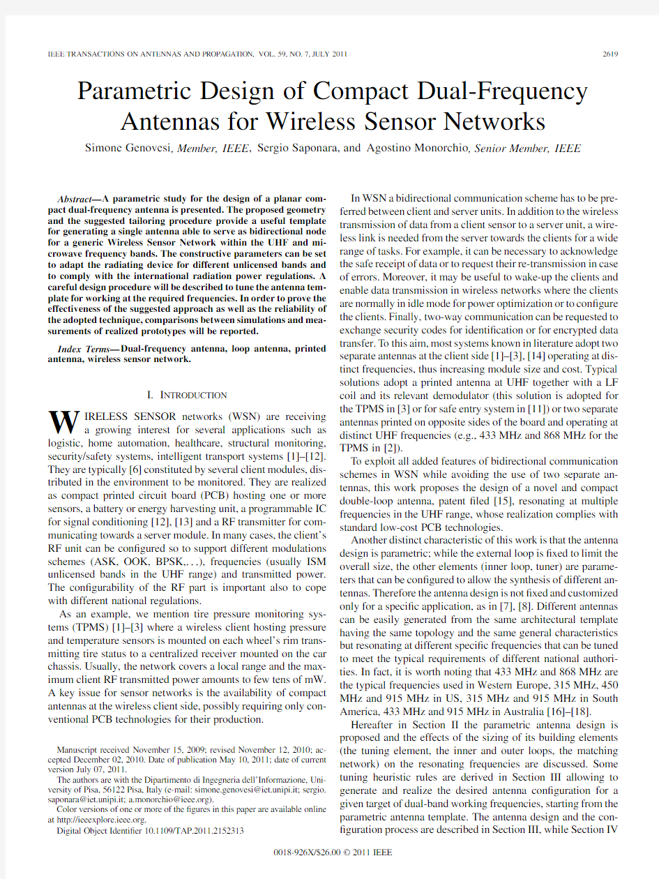
Fig.1.Top view of the antenna template.
illustrates the generation,realization and measurements of distinct multi-frequencies antennas presented as case studies.Section V proves that the achieved performances of the novel proposed antennas are useful to realize wireless networking systems compliant with the radiation power regulations (US FCC [19]and ETSI [20]).Finally,conclusions are drawn in Section 6.
II.A NTENNA T EMPLATE D ESCRIPTION
The con?guration of the antenna comprises an outer loop,an inner loop and a tuning element (Fig.1).The outer loop is connected to the source,or the electronic circuitry,by using a simple matching network.In order to show the effect of each single basic element of the antenna template,we consider the investigated radiating device printed on a commercially avail-able dielectric substrate
(
mm)and a trace width equal to 1.25mm.It is important to point out that we are interested in the impedance of the antenna determined at the open ends of the outer loop.This feeding con?guration allows the antenna to be easily connected to electronic circuitry and RFIC input/output and,at the same time,prevents the use of balun or via-hole.The width of the trace equal to 1.25mm has been chosen according to the solutions commonly adopted in commercial devices but a slightly different width can be em-ployed to perform the design process.As an example,an outer
loop of ?xed
dimension
cm has been chosen to perform our parametric analysis but different sizes can be adopted depending on the available space on the PCB.These dimensions refer to the solution proposed in [3];however,as additional advantage,we now propose an antenna design that occupies the same area but supports multiple frequencies.It is important to highlight that the perimeter of the outer loop is re-lated to the value of the higher resonance,as it will be deeply discussed in the following.Therefore,a good starting guess for the size is represented by an outer loop with a perimeter close to the free-space wavelength at the higher frequency (we can ?nd the same resonance frequency by using,for instance,di-mensions of 4.2
cm 4.2cm instead of 5.3
cm 3.2cm
since
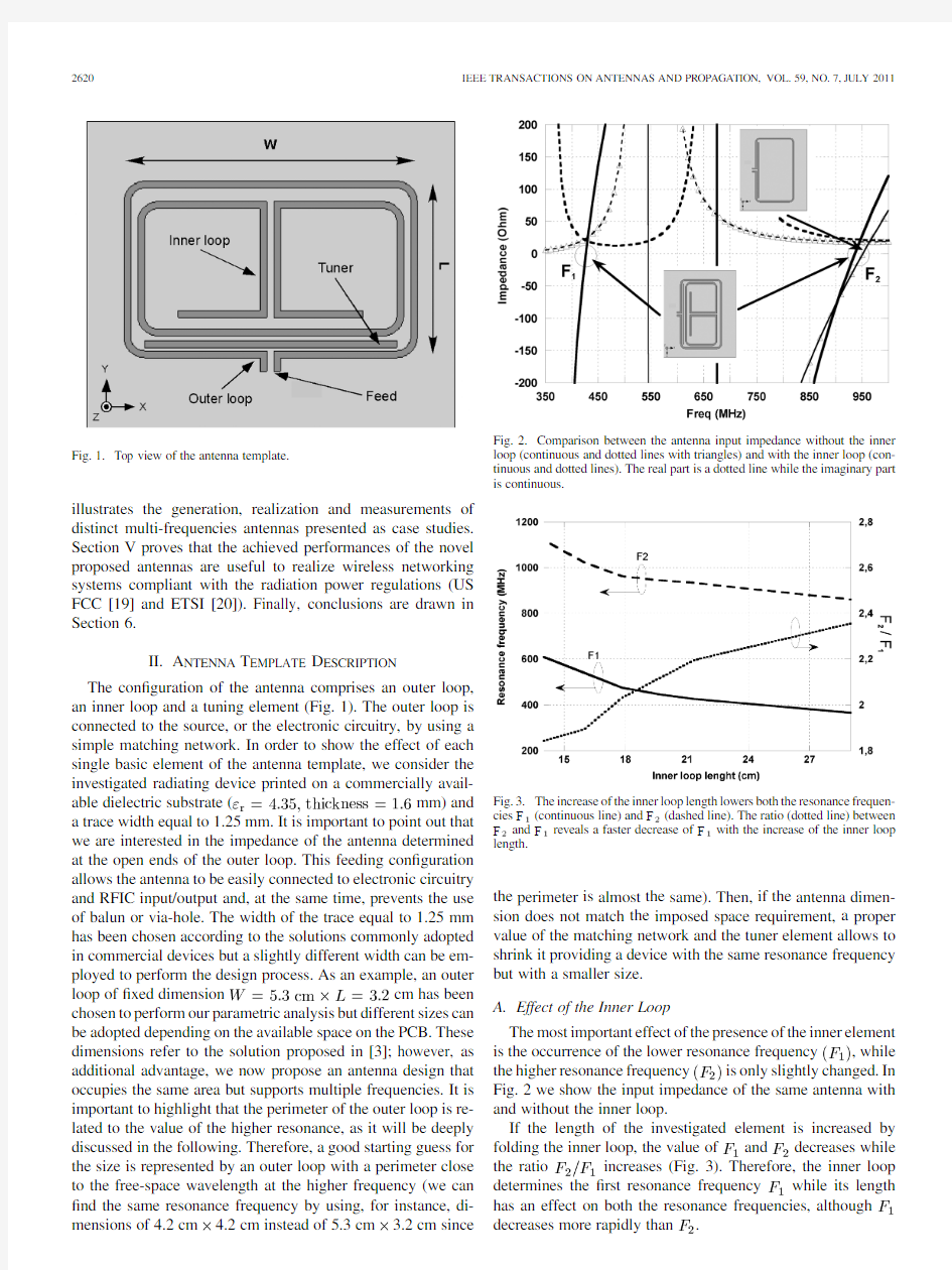
https://www.sodocs.net/doc/754468181.html,parison between the antenna input impedance without the inner loop (continuous and dotted lines with triangles)and with the inner loop (con-tinuous and dotted lines).The real part is a dotted line while the imaginary part is
continuous.
Fig.3.The increase of the inner loop length lowers both the resonance frequen-cies F (continuous line)and F (dashed line).The ratio (dotted line)between F and F reveals a faster decrease of F with the increase of the inner loop length.
the perimeter is almost the same).Then,if the antenna dimen-sion does not match the imposed space requirement,a proper value of the matching network and the tuner element allows to shrink it providing a device with the same resonance frequency but with a smaller size.A.Effect of the Inner Loop
The most important effect of the presence of the inner element
is the occurrence of the lower resonance
frequency
,while the higher resonance
frequency
is only slightly changed.In Fig.2we show the input impedance of the same antenna with and without the inner loop.
If the length of the investigated element is increased by
folding the inner loop,the value
of
and decreases while the
ratio
increases (Fig.3).Therefore,the inner loop determines the ?rst resonance
frequency
while its length has an effect on both the resonance frequencies,
although decreases more rapidly
than .
GENOVESI et al.:PARAMETRIC DESIGN OF COMPACT DUAL-FREQUENCY ANTENNAS FOR WIRELESS SENSOR NETWORKS
2621
Fig.4.Changes in the inner loop position (a),determine an effect of the inner loop position on both resonance frequencies
(b).
https://www.sodocs.net/doc/754468181.html,parison between the antenna input impedance without the tuning element (continuous and dotted lines with triangles)and with the inner loop (continuous and dotted lines).The real part is a dotted line while the imaginary part is continuous.
The position of the inner loop in?uences the resonance fre-quencies.In Fig.4it is possible to observe that increasing the offset (Fig.4(a))between the tuner and the inner loop raises F2while F1slightly decreases (Fig.4(b)).In particular,the
value of
the
dB bandwidth for the ?rst resonance remains stable around 1.0%whereas for the second one we obtain 1.5%.These values are typical for wireless sensor network applica-tions where the amount of information to be transferred requires low bit-rates and they also agree with the ones presented in [9].Therefore,although the resonance frequencies shift as shown in Fig.4,the impedance bandwidth is not affected and remains stable for all offsets.
B.Effect of the Tuning Element
The length of the tuning element placed between the outer
and the inner loop affects the value
of
and produces a small variation
of
(Fig.5).More in detail,if we increase the length of the tuning
element,decreases as well as the
ratio (Fig.
6).
Fig.6.The increase of the tuner length slightly changes F (continuous line)while F (dashed line)shifts toward lower values.The ratio between F and F (dotted line)decreases in the investigated range (no tuner-4.6
cm).
Fig.7.Higher values of the inductance in the matching network determine smaller values of both the resonance frequencies although F (dashed line)de-crease more rapidly than F (continuous line),as the ratio between F and F (dotted line)highlights.
C.Effect of the Matching Network
The matching network considered for the study comprises
only an inductance connected to the outer loop.The considered inductance is in the range of tens of nH.For these values sur-face mount inductors exist that can be easily soldered to the PCB trace just before the source or the electronic circuitry.As shown in Fig.7,the increase of the inductance value determines a shift toward lower resonance frequencies whereas the real part of the input impedance at the resonance varies within a set of reason-able values for the realization of a standard matching network (Fig.8).
III.T UNING OF THE A NTENNA T EMPLATE
Each element of the antenna template has to be carefully di-mensioned and tuned in order to obtain the desired resonance frequencies.In particular,as pointed out in the previous section,even a single change in one element affects both the resonance
frequencies
and and their
ratio .This section will provide guidelines to exploit the antenna framework for the de-sign of an antenna with two resonances within the ISM band at
the desired
frequencies
and .
2622IEEE TRANSACTIONS ON ANTENNAS AND PROPAGATION,VOL.59,NO.7,JULY
2011
Fig.8.The real part of the input impedance is within an acceptable range of values for both the frequencies F (continuous line)and F (dashed line).
As well known,the design can be subject to a series of limi-tations such as the allowed space for the radiating device or the discrete values assumed by the lumped loads of the matching network.As a case study,we consider again the dimensions of the outer loop equal to 5.3
cm 3.2cm in order to design an antenna with two resonance frequencies satisfying the Australia
requirements
(
MHz
and MHz).The ?rst step is to obtain an antenna with a
resonance and,at the same time,a
resonance .Basically,this means that we have to tune the framework in order to achieve the ?rst resonance by choosing a proper matching network and the inner loop length.To accomplish this goal,we set the tuner element as long as possible at this stage since its function will
be to increase the value
of in order to make the antenna res-onating also
at .The aforementioned rules will suggest the changes that have to be made to the length or the position of the elements.For example,in order to increase the ?rst resonance we have to decrease the inner loop size or the value of the in-ductance of the matching network.
Suppose we start our tuning procedure with a matching net-work comprising an inductance of 33nH and an inner loop with a length of 25cm.In this case,we have a value
of around 380MHz and a second resonance
frequency around 870MHz.To allow our framework to satisfy the requirements of the ?rst step we need to decrease the inner loop until its length is equal to
19.5cm.and
hence
with MHz.Next,
since ,we have still to tune the second resonance frequency
and therefore we reduce the tuner element from 2.3cm to 2.15
cm to
obtain
.All the presented results have been val-idated by using Ansoft HFSS [21]and are reported in Fig.9.
IV .M EASUREMENTS
The procedure described in the previous section has been successfully applied for different sets of resonance frequencies,also including all the resonance frequencies mentioned in Section I.Moreover,in order to validate the simulated results,two prototypes have been realized and measured.The former is an antenna with two resonances in accordance with
the
Fig.9.Tuning of the antenna framework.The dotted lines are the real part of input impedances while the continuous lines illustrate the imaginary parts.The lines with triangles refers to the starting con?guration with F =380MHz and F =870MHz,the lines with circles to the antenna with F =F and the remaining lines to the ?nal antenna satisfying the imposed
requirements.
Fig.10.Front view of the prototype for the double loop antenna satisfying the requirements of Australia resonance frequencies.
Australia requirements whereas the latter complies with the South America standard.
An half-loop version of both of the antennas was fabricated (Figs.10and 11)and its measured input impedance was com-pared to the simulated results.We recurred to an half-loop ver-sion for the fabrication because it allows to validate the antenna performance while preventing the need to design and build a balun for the antenna.The dimensions of the half-loop antennas were determined by using HFSS,following the aforementioned rules for the tuning.More in detail,the tuner length is equal to 4cm and the inner element is 21.5cm long for the Aus-tralia con?guration while the tuner is 4.6cm and the inner ele-ment is 39cm length for the South America antenna.Each de-vice was printed on a commercially available dielectric substrate
(
mm)with a trace width equals to 1.25mm.
The antenna is excited via a SMA connector with the outer conductor connected directly to the ground plane and the center conductor connected to the matching network of outer conductor of the half-loop.According to images’theorem,the impedance of an half-loop above an in?nite ground plane is
GENOVESI et al.:PARAMETRIC DESIGN OF COMPACT DUAL-FREQUENCY ANTENNAS FOR WIRELESS SENSOR NETWORKS
2623
Fig.11.Front view of the prototype for the double loop antenna satisfying the requirements of South America resonance
frequencies.
https://www.sodocs.net/doc/754468181.html,parison between simulation (lines)and measurements (dots)of the input impedance related to the ?rst resonance (433MHz)of Australia con?g-uration:real part (continuous line)and imaginary part (dashed line)are shown.
equal to one-half of the corresponding full loop.If the ground plane is suf?ciently large,this statement still holds and we can use it to estimate the impedance of the half-loop.The input impedances of the fabricated half-loops were used to estimate the performance of the radiating device and comparisons with the numerical results have been reported in order to assess the reliability of the proposed design procedure.A Wiltron 37311A network analyzer was used to measure the input impedance versus frequency of the fabricated prototypes.
In Fig.12we compare the real and imaginary part of the sim-ulated and measured input impedance at the ?rst and second resonance of the Australia con?guration,respectively.The real part of the measured input impedance for the ?rst resonance is in good agreement with the simulated one and also the measured imaginary part is close to the computed one since there is only a 4%off-set discrepancy with respect to the expected resonance frequency of 433MHz (mainly due to technology and compo-nent spreading for the adopted manufacturing process).
The real part of the measured input impedance for the second resonance (Fig.13)exhibits a behavior similar to the simulated curve whereas the imaginary part is quite close to the expected one of 915MHz (0.14%of discrepancy).
The comparison between the real and imaginary part of the input impedance for the South America con?guration is shown in Fig.14for the ?rst resonance.The measured real part of
the
https://www.sodocs.net/doc/754468181.html,parison between simulation (lines)and measurements (dots)of the input impedance related to the second resonance (915MHz)of Australia con?guration:real part (continuous line)and imaginary part (dashed line)are
shown.
https://www.sodocs.net/doc/754468181.html,parison between simulation (lines)and measurements (dots)of the input impedance related to the ?rst resonance of South America con?gura-tion:real part (continuous line)and imaginary part (dashed line)are shown.
impedance at the ?rst resonance is in accordance with the simu-lated results and also the imaginary part of the prototype is close to the expected 315MHz (4%of discrepancy).At the second resonance,the real part of the input impedance (Fig.15)has a similar trend to the simulated one and assumes acceptable values whereas the imaginary part is quite close to the estimated one (2.29%of discrepancy).
The simulated results are in good agreement with the mea-sured one,therefore the proposed procedure for the design can be considered reliable.The small discrepancy (always below 4%)could be determined by a series of different causes such as the tolerance of the components (5%for the inductance of the matching network),the effect of the welding in the half-loop prototypes,a non ideal insertion of the SMA connector to the antenna and the ground plane.However,a further tuning can be easily done by trimming the printed antenna.
V .R ADIATION P ATTERN AND L INK B UDGET
In order to characterize the performance of the proposed an-tenna con?guration,radiation patterns for the Australian and
2624IEEE TRANSACTIONS ON ANTENNAS AND PROPAGATION,VOL.59,NO.7,JULY
2011
https://www.sodocs.net/doc/754468181.html,parison between simulation (lines)and measurements (dots)of the input impedance related to the second resonance of South America con?g-uration:real part (continuous line)and imaginary part (dashed line)are shown.
South American con?guration are reported in Figs.16and 17,respectively.As it can be noticed,the pattern retains an om-nidirectional behavior on the horizontal plane for both reso-nance frequencies for the Australian as well as the South Amer-ican con?guration,thus providing a good connection among the nodes of the sensing network.
The gain values of the Australia con?guration are equal
to
dB
and dB while those of the South America con-?guration
are
dB
and dB respectively at the ?rst and second resonance.The values of the gain are comparable to those ?nd in [9]and [10]which are recent works in literature targeting similar applications of that considered in our paper.Since the proposed antenna can be employed in the sensing node of a wireless system,it has to be compliant with the radia-tion power regulations (US FCC and ETSI).Let us consider our antenna on each sensing node and a standard patch antenna (7.0dB of gain),working at the same frequencies,at the master node.The MCU (Micro Controller Unit)in the master node generally hosts an RF transceiver able to receive signals with a sensitivity
below
dBm,therefore the sensing node has to deliver a very low power level.At this purpose,currents of a few mA are suf?cient [2],[3]for the sensing node to transmit an intel-ligible signal to the master node.On the other side,particularly in passively-powered [22],[23]or power-optimized [2]sensor networks,the sensing node has an RF recti?er,which delivers outputs compliant with standard microcontroller voltage levels.The RF recti?ers can work properly if the received power at the
antenna is in the range
of
dBm
to dBm,depending on the implementation technology [22],[23].
For the case of Australian con?guration,the sensing unit communicates with the master node at 433MHz and the master node uses an RF link at 915MHz to send data to the sensing node.
By using the well known Friis formula in the maximum ra-diation condition and by supposing a distance between trans-mitter and receiver equals to 3.0m,the required power for the 915MHz transmitter master node ranges from tens of mW up to 105mW (Fig.18),well below the allowed transmitter
power
Fig.16.Normalized radiation pattern for Australia con?guration at (a)?rst res-onance of 433MHz;(b)second resonance 915MHz.The line with dot markers refers to the =0cut,the triangular markers to the =90cut and the square markers to =90plane.
limit (500mW).The aforementioned sensitivity of the MCU RF transceiver guarantees the link at 433MHZ to work prop-erly with much less power.
In order to assess the maximum possible communication distance and hence the covered range of the system,we have studied the necessary level of transmitted power with the increment of the distance between the RF transceiver of the master node and the receiver at the sensing node.As already mentioned,if we consider a distance of 3.0m we need to transmit few tens of mWs if we employ a performing RF
recti?er
(
dBm)or around 100mW if we use an ordinary
中国姓氏英文翻译大全S-Z
A: 艾--Ai 安--Ann/An 敖--Ao B: 巴--Pa 白--Pai 包/鲍--Paul/Pao 班--Pan 贝--Pei 毕--Pih 卞--Bein 卜/薄--Po/Pu 步--Poo 百里--Pai-li C: 蔡/柴--Tsia/Choi/Tsai 曹/晁/巢--Chao/Chiao/Tsao 岑--Cheng 崔--Tsui 查--Cha 常--Chiong 车--Che 陈--Chen/Chan/Tan 成/程--Cheng 池--Chi 褚/楚--Chu 淳于--Chwen-yu D: 戴/代--Day/Tai 邓--Teng/Tang/Tung 狄--Ti 刁--Tiao 丁--Ting/T 董/东--Tung/Tong 窦--Tou 杜--To/Du/Too 段--Tuan 端木--Duan-mu 东郭--Tung-kuo 东方--Tung-fang E: F:
范/樊--Fan/Van 房/方--Fang 费--Fei 冯/凤/封--Fung/Fong 符/傅--Fu/Foo G: 盖--Kai 甘--Kan 高/郜--Gao/Kao 葛--Keh 耿--Keng 弓/宫/龚/恭--Kung 勾--Kou 古/谷/顾--Ku/Koo 桂--Kwei 管/关--Kuan/Kwan 郭/国--Kwok/Kuo 公孙--Kung-sun 公羊--Kung-yang 公冶--Kung-yeh 谷梁--Ku-liang H: 海--Hay 韩--Hon/Han 杭--Hang 郝--Hoa/Howe 何/贺--Ho 桓--Won 侯--Hou 洪--Hung 胡/扈--Hu/Hoo 花/华--Hua 宦--Huan 黄--Wong/Hwang 霍--Huo 皇甫--Hwang-fu 呼延--Hu-yen I: J: 纪/翼/季/吉/嵇/汲/籍/姬--Chi 居--Chu 贾--Chia 翦/简--Jen/Jane/Chieh 蒋/姜/江/--Chiang/Kwong 焦--Chiao 金/靳--Jin/King 景/荆--King/Ching
图像处理中值滤波器中英文对照外文翻译文献
中英文资料对照外文翻译 一、英文原文 A NEW CONTENT BASED MEDIAN FILTER ABSTRACT In this paper the hardware implementation of a contentbased median filter suitabl e for real-time impulse noise suppression is presented. The function of the proposed ci rcuitry is adaptive; it detects the existence of impulse noise in an image neighborhood and applies the median filter operator only when necessary. In this way, the blurring o f the imagein process is avoided and the integrity of edge and detail information is pre served. The proposed digital hardware structure is capable of processing gray-scale im ages of 8-bit resolution and is fully pipelined, whereas parallel processing is used to m inimize computational time. The architecturepresented was implemented in FPGA an d it can be used in industrial imaging applications, where fast processing is of the utm ost importance. The typical system clock frequency is 55 MHz. 1. INTRODUCTION Two applications of great importance in the area of image processing are noise filtering and image enhancement [1].These tasks are an essential part of any image pro cessor,whether the final image is utilized for visual interpretation or for automatic an alysis. The aim of noise filtering is to eliminate noise and its effects on the original im age, while corrupting the image as little as possible. To this end, nonlinear techniques (like the median and, in general, order statistics filters) have been found to provide mo re satisfactory results in comparison to linear methods. Impulse noise exists in many p ractical applications and can be generated by various sources, including a number of man made phenomena, such as unprotected switches, industrial machines and car ign ition systems. Images are often corrupted by impulse noise due to a noisy sensor or ch annel transmission errors. The most common method used for impulse noise suppressi on n forgray-scale and color images is the median filter (MF) [2].The basic drawback o f the application of the MF is the blurringof the image in process. In the general case,t he filter is applied uniformly across an image, modifying pixels that arenot contamina ted by noise. In this way, the effective elimination of impulse noise is often at the exp ense of an overalldegradation of the image and blurred or distorted features[3].In this paper an intelligent hardware structure of a content based median filter (CBMF) suita ble for impulse noise suppression is presented. The function of the proposed circuit is to detect the existence of noise in the image window and apply the corresponding MF
技术开发部管理手册1
目录 第1章概述 (1) 1.1 技术开发部管理权限 (1) 1.2 技术开发部管理职能 (1) 1.3 技术开发部主要职责 (1) 1.4 日常管理制度 (2) 第2章产品开发设计控制程序 (4) 2.1 目的 (4) 2.2 范围 (5) 2.3 引用文件及术语 (5) 2.4 职责 (5) 2.5 工作程序 (6) 2.6 支持文件 (9) 2.7 表格清单 (9) 2.8 附表 (9) 第3章产品实现的策划程序 (17) 3.1 目的 (17) 3.2 适应范围 (17) 3.3 引用文件及术语 (18) 3.4 职责 (18) 3.5 工作程序 (18) 3.6 支持性文件 (19) 第4章内部质量审核控制程序 (20) 4.1 目的 (20) 4.2 适用范围 (20) 4.3 引用文件及术语 (20) 4.4 职责 (20) 4.5 工作程序 (21) 4.6 支持文件 (23) 4.7 质量记录 (23) 附录 (25) 附录1 (25) 附录2 (26) 附录3 (27) 附录5 (29) 附录6 (30) 附件7 (31) 附件8 (32)
第1章概述 技术开发部的工作主要是从事电表、水表、煤气表及其远程自动抄系统的研发和产品的优化,以及为生产部和工程部提供技术支持等。 1.1 技术开发部管理权限 受总经理和技术总监委托,行使对公司技术引进、新产品开发研究、新技术推广应用、技术指导与监督等全过程听管理权限,并承担执行公司规章制度、管理规程及工作指令的义务; 1.2 技术开发部管理职能 负责对公司产品实行技术指导、规范工艺流程、制定技术标准、抓好技术管理、实施技术监督和协调的专职管理部门,对所承担的工作负责。 1.3 技术开发部主要职责: 1.坚决服从总经理和技术总监的统一指挥,认真执行其工作指令,一切管理行为向总经理和技术总监负责; 2.严格遵守公司规章制度,认真履行其工作职责; 3.负责制定公司技术管理制度。负责建立和完善产品设计、新产品的试制、标准化技术规程、技术情报管理制度,组织、协调、督促有关部门建立和完善设备、质量、能源等管理标准及制度; 4.组织和编制公司技术发展规划。编制近期技术提高工作计划,编制长远技术发展和技术措施规划,并组织对计划、规划的拟定、修改、补充、实施等一系列技术组织和管理工作; 5.负责制订和修改技术规程。编制产品的使用、维修和技术安全等有关的技术规定; 6.负责公司新技术引进和产品开发工作的计划、实施,确保产品品种不断更新和扩大; 7.合理编制技术文件,改进和规范工艺流程; 8.研究和摸索科学的流水作业规律,认真做好各类技术信息和资料收集、整理、分析、研究汇总、归档保管工作,为逐步实现公司现代化销售的目标,提供可靠的指导依据; 9.负责制定公司产品的企业统一标准,实现产品的规范化管理; 10.编制公司产品标准,按年度审核、补充、修订定额内容;
中国姓氏英语翻译大全
中国姓氏英语翻译大全 A: 艾--Ai 安--Ann/An 敖--Ao B: 巴--Pa 白--Pai 包/鲍--Paul/Pao 班--Pan 贝--Pei 毕--Pih 卞--Bein 卜/薄--Po/Pu 步--Poo 百里--Pai-li C: 蔡/柴--Tsia/Choi/Tsai 曹/晁/巢--Chao/Chiao/Tsao 岑--Cheng 崔--Tsui 查--Cha
常--Chiong 车--Che 陈--Chen/Chan/Tan 成/程--Cheng 池--Chi 褚/楚--Chu 淳于--Chwen-yu D: 戴/代--Day/Tai 邓--Teng/Tang/Tung 狄--Ti 刁--Tiao 丁--Ting/T 董/东--Tung/Tong 窦--Tou 杜--To/Du/Too 段--Tuan 端木--Duan-mu 东郭--Tung-kuo 东方--Tung-fang E: F:
范/樊--Fan/Van 房/方--Fang 费--Fei 冯/凤/封--Fung/Fong 符/傅--Fu/Foo G: 盖--Kai 甘--Kan 高/郜--Gao/Kao 葛--Keh 耿--Keng 弓/宫/龚/恭--Kung 勾--Kou 古/谷/顾--Ku/Koo 桂--Kwei 管/关--Kuan/Kwan 郭/国--Kwok/Kuo 公孙--Kung-sun 公羊--Kung-yang 公冶--Kung-yeh 谷梁--Ku-liang H:
韩--Hon/Han 杭--Hang 郝--Hoa/Howe 何/贺--Ho 桓--Won 侯--Hou 洪--Hung 胡/扈--Hu/Hoo 花/华--Hua 宦--Huan 黄--Wong/Hwang 霍--Huo 皇甫--Hwang-fu 呼延--Hu-yen I: J: 纪/翼/季/吉/嵇/汲/籍/姬--Chi 居--Chu 贾--Chia 翦/简--Jen/Jane/Chieh 蒋/姜/江/--Chiang/Kwong
图像处理外文翻译 (2)
附录一英文原文 Illustrator software and Photoshop software difference Photoshop and Illustrator is by Adobe product of our company, but as everyone more familiar Photoshop software, set scanning images, editing modification, image production, advertising creative, image input and output in one of the image processing software, favored by the vast number of graphic design personnel and computer art lovers alike. Photoshop expertise in image processing, and not graphics creation. Its application field, also very extensive, images, graphics, text, video, publishing various aspects have involved. Look from the function, Photoshop can be divided into image editing, image synthesis, school tonal color and special effects production parts. Image editing is image processing based on the image, can do all kinds of transform such as amplifier, reducing, rotation, lean, mirror, clairvoyant, etc. Also can copy, remove stain, repair damaged image, to modify etc. This in wedding photography, portrait processing production is very useful, and remove the part of the portrait, not satisfied with beautification processing, get let a person very satisfactory results. Image synthesis is will a few image through layer operation, tools application of intact, transmit definite synthesis of meaning images, which is a sure way of fine arts design. Photoshop provide drawing tools let foreign image and creative good fusion, the synthesis of possible make the image is perfect. School colour in photoshop with power is one of the functions of deep, the image can be quickly on the color rendition, color slants adjustment and correction, also can be in different colors to switch to meet in different areas such as web image design, printing and multimedia application. Special effects production in photoshop mainly by filter, passage of comprehensive application tools and finish. Including image effects of creative and special effects words such as paintings, making relief, gypsum paintings, drawings, etc commonly used traditional arts skills can be completed by photoshop effects. And all sorts of effects of production are
汽车新产品质量管理手册
浙江吉利控股集团有限公司企业标准
浙江吉利控股集团有限公司 新产品质量管理手册 (第1版)V1.0 浙江吉利控股集团有限公司 2011-11-25发布 2011-12-30实施
说明 为贯彻集团“两个转型”和“两个调整”的经营工作思路,实现从“产品线管理”向“品牌线管理”的调整,规范和细化集团新产品项目质量管理过程,明确质量系统各单位在新产品质量管理过程中的职责及工作内容,使实际工作开展有规可循,并强化可操作性,特制定此《吉利集团新产品质量管理手册》(第1版),版本号为V1.0。
目录 第一章新产品质量管理总则 第二章新产品质量评审流程 第三章新产品品熟推进流程 第四章附录
第一章 新产品质量管理总则 1.1目的 为了规范集团新产品开发各阶段的质量管理,促进各部门在新品阶段的质量自主管理能力,并以用户满意为最终目标,展开各阶层新产品质量管理。 1.2范围 本手册适用于以下项目范围:整车开发项目,发动机开发项目,变速器开发项目等各类将以量产形式生产并销售的新产品正式立项开发项目(具体项目分类界定规则参照《研发项目管理办法 V2.1》,涉及具体工作开展项目范围时,可由关联单位协商界定)。 1.3新产品质量管理模式 集团新产品质量管理采用由集团质量管理部建立统一的管理体系,各品牌质量部主导策划管控及实施,各系统分级管控的模式。通过前期的弱点项目(雷区项目)设计输入、依托各新产品项目品熟团队,以不断循环展开的阶段质量阀评审以及品熟活动,达成新产品质量保证,最终实现用户满意。新产品质量管理对新产品整体项目质量负责,确保新产品项目质量达标,满足设计和市场要求。新产品质量管理绩效评价按集团质量部相关考核指标展开(参看集团质量体系考核相关文件)。 1.3.1新产品质量管控过程 新产品质量管理涉及集团项目管理流程全部三个阶段: 1.3.1.1立项阶段的质量管控 在新产品立项阶段,质量部门负责项目质量策划,并向项目组输出项目各阶段项目质量目标、《质量目标保障计划书》,以及过往和在产产品设计相关弱点问题清单(雷区项目),全部内容均可包含在《质量目标保障计划书》中一并提交。 1.3.1.1.1 新产品质量目标的策划(包括各开发试制阶段及量产阶段) ·质量目标设定的原则: -新产品质量目标的设定应与集团的经营战略相一致; -新产品的质量目标应根据车型平台特征、市场分析、过往质量水平进行各阶段的目标设定(数据来源包括设计、采购、制造、市场等各产品过程相关部门),并在各阶段质量评审中进行考评; -质量目标应包括反映设计改善、制造、市场、供应商品质等各领域产品及过程相关的指标内容,具体可根据项目实际进行增加或删减。基础项目请参考《第四章 附录》中的《质量目标基础项目表》。 目标设定后应向各质量责任单元分解,并制定相应的质量目标保障措施。 立项阶段 实施与控制阶段 关闭阶段
双语:中国姓氏英文翻译对照大合集
[ ]
步Poo 百里Pai-li C: 蔡/柴Tsia/Choi/Tsai 曹/晁/巢Chao/Chiao/Tsao 岑Cheng 崔Tsui 查Cha 常Chiong 车Che 陈Chen/Chan/Tan 成/程Cheng 池Chi 褚/楚Chu 淳于Chwen-yu
D: 戴/代Day/Tai 邓Teng/Tang/Tung 狄Ti 刁Tiao 丁Ting/T 董/东Tung/Tong 窦Tou 杜To/Du/Too 段Tuan 端木Duan-mu 东郭Tung-kuo 东方Tung-fang F: 范/樊Fan/Van
房/方Fang 费Fei 冯/凤/封Fung/Fong 符/傅Fu/Foo G: 盖Kai 甘Kan 高/郜Gao/Kao 葛Keh 耿Keng 弓/宫/龚/恭Kung 勾Kou 古/谷/顾Ku/Koo 桂Kwei 管/关Kuan/Kwan
郭/国Kwok/Kuo 公孙Kung-sun 公羊Kung-yang 公冶Kung-yeh 谷梁Ku-liang H: 海Hay 韩Hon/Han 杭Hang 郝Hoa/Howe 何/贺Ho 桓Won 侯Hou 洪Hung 胡/扈Hu/Hoo
花/华Hua 宦Huan 黄Wong/Hwang 霍Huo 皇甫Hwang-fu 呼延Hu-yen J: 纪/翼/季/吉/嵇/汲/籍/姬Chi 居Chu 贾Chia 翦/简Jen/Jane/Chieh 蒋/姜/江/ Chiang/Kwong 焦Chiao 金/靳Jin/King 景/荆King/Ching
图像处理中常用英文词解释
Algebraic operation 代数运算一种图像处理运算,包括两幅图像对应像素的和、差、积、商。 Aliasing 走样(混叠)当图像像素间距和图像细节相比太大时产生的一种人工痕迹。Arc 弧图的一部分;表示一曲线一段的相连的像素集合。 Binary image 二值图像只有两级灰度的数字图像(通常为0和1,黑和白) Blur 模糊由于散焦、低通滤波、摄像机运动等引起的图像清晰度的下降。 Border 边框一副图像的首、末行或列。 Boundary chain code 边界链码定义一个物体边界的方向序列。 Boundary pixel 边界像素至少和一个背景像素相邻接的内部像素(比较:外部像素、内部像素) Boundary tracking 边界跟踪一种图像分割技术,通过沿弧从一个像素顺序探索到下一个像素将弧检测出。 Brightness 亮度和图像一个点相关的值,表示从该点的物体发射或放射的光的量。 Change detection 变化检测通过相减等操作将两幅匹准图像的像素加以比较从而检测出其中物体差别的技术。 Class 类见模或类 Closed curve 封闭曲线一条首尾点处于同一位置的曲线。 Cluster 聚类、集群在空间(如在特征空间)中位置接近的点的集合。 Cluster analysis 聚类分析在空间中对聚类的检测,度量和描述。 Concave 凹的物体是凹的是指至少存在两个物体内部的点,其连线不能完全包含在物体内部(反义词为凸) Connected 连通的 Contour encoding 轮廓编码对具有均匀灰度的区域,只将其边界进行编码的一种图像压缩技术。 Contrast 对比度物体平均亮度(或灰度)与其周围背景的差别程度 Contrast stretch 对比度扩展一种线性的灰度变换 Convex 凸的物体是凸的是指连接物体内部任意两点的直线均落在物体内部。Convolution 卷积一种将两个函数组合成第三个函数的运算,卷积刻画了线性移不变系统的运算。 Corrvolution kernel 卷积核1,用于数字图像卷积滤波的二维数字阵列,2,与图像或信号卷积的函数。 Curve 曲线1,空间的一条连续路径,2 表示一路径的像素集合(见弧、封闭曲线)。 Deblurring 去模糊1一种降低图像模糊,锐化图像细节的运算。2 消除或降低图像的模糊,通常是图像复原或重构的一个步骤。 Decision rule 决策规则在模式识别中,用以将图像中物体赋以一定量的规则或算法,这种赋值是以对物体特征度量为基础的。 Digital image 数字图像 1 表示景物图像的整数阵列,2 一个二维或更高维的采样并量化的函数,它由相同维数的连续图像产生,3 在矩形(或其他)网络上采样一连续函数,并才采样点上将值量化后的阵列。 Digital image processing 数字图像处理对图像的数字化处理;由计算机对图片信息进
(完整版)新产品开发项目管理制度
新产品开发项目管理制度 1.目的和作用 新产品开发是企业在激烈的技术竞争中赖以生存和发展的命脉,它对企业产品发展方向、产品优势、开拓新市场、提高经济效益等方面起着决定性作用。为了使新产品开发能够严格遵循科学管理程序进行,取得较好的效果,特制定本制度。 2.管理职责 2.1统筹规划部负责新产品的调研分析与立项等方面的工作。 2.2技术研发部负责产品的设计、试制、鉴定、移交投产等方面的管理。 2.3物控部、生产部、质管部应在整个开发过程中给予支持和配合。 3.新产品开发的前期调研分析工作 新产品的可行性分析是新产品开发不可缺少的前期工作,必须在进行充分的技术和市场调查后,对产品的社会需要、市场占有率、技术现状、发展趋势以及资源效益等五个方面进行科学预测及经济性的分析论证。 3.1 调查研究: 3.1.1 调查国内市场和重要用户以及国际重点市场的技术现状和改进要求. 3.1.2 以国内同类产品市场占有率高的前三名以及国际名牌产品为对象,调查同类产品的质量、价格及使用情况。
3.1.3 广泛收集国内外有关情报和专利,然后进行可行性分析研究. 3.2 可行性分析: 3.2.1 论证该产品的技术发展方向和动向. 3.2.2 论证市场动态及发展该产品具备的技术优势. 3.2.3 论证该产品发展所具备的资源条件和可行性(含物资、设备、能源、外购外协配套等)。 3.2.4 初步论证技术经济效益。 3.2.5 写出该产品批量投产的可行性分析报告。 4. 产品设计管理 产品设计时从确定产品设计任务书起到确定产品结构为止的一系 列技术工作的准备和管理,是产品开发的重要环节,必须严格遵循"三 段设计"程序. 4.1 技术任务书: 技术任务书市产品在初步设计阶段内,由设计部门向上级提出的 体现产品合理设计方案的改进性和推存性意见的文件,经上级批准后,作为产品技术设计的依据.其目的在于正确地确定产品的最佳总体设计方案、主要技术性能参数、工作原理、系统和主体结构,并由设计员负责编写(其中标准化规则要求会同标准化人员共同拟定)。现对其编写内容和程序作如下规定: 4.1.1 设计依据(根据具体情况可以包括一个或数个内容): a. 国内外技术情报:在市场的性能和使用性方面赶超国内外先进水平,或在产品品种方面填补国内"空白".
中国姓氏英语翻译大全
中国姓氏英语翻译大全 A: 艾--Ai 安--Ann/An 敖--Ao B: 巴--Pa 白--Pai 包/鲍--Paul/Pao 班--Pan 贝--Pei 毕--Pih 卞--Bein 卜/薄--Po/Pu 步--Poo 百里--Pai-li C: 蔡/柴--Tsia/Choi/Tsai 曹/晁/巢--Chao/Chiao/Tsao 岑--Cheng 崔--Tsui 查--Cha 常--Chiong 车--Che 陈--Chen/Chan/Tan 成/程--Cheng 池--Chi 褚/楚--Chu 淳于--Chwen-yu D: 戴/代--Day/Tai 邓--Teng/Tang/Tung 狄--Ti 刁--Tiao 丁--Ting/T 董/东--Tung/Tong 窦--Tou 杜--To/Du/Too 段--Tuan 端木--Duan-mu 东郭--Tung-kuo 东方--Tung-fang E: F: 范/樊--Fan/Van 房/方--Fang 费--Fei 冯/凤/封--Fung/Fong 符/傅--Fu/Foo G: 盖--Kai 甘--Kan 高/郜--Gao/Kao 葛--Keh 耿--Keng 弓/宫/龚/恭--Kung 勾--Kou 古/谷/顾--Ku/Koo 桂--Kwei 管/关--Kuan/Kwan 郭/国--Kwok/Kuo 公孙--Kung-sun 公羊--Kung-yang 公冶--Kung-yeh 谷梁--Ku-liang H: 海--Hay 韩--Hon/Han 杭--Hang 郝--Hoa/Howe 何/贺--Ho 桓--Won 侯--Hou 洪--Hung 胡/扈--Hu/Hoo 花/华--Hua 宦--Huan 黄--Wong/Hwang 霍--Huo 皇甫--Hwang-fu 呼延--Hu-yen I: J: 纪/翼/季/吉/嵇/汲/籍/姬--Chi
新产品开发的管理制度
新产品开发管理制度 新产品开发工作,是指运用国内外在基础研究与应用研究中所发现的科学知识及其成果,转变为新产品、新材料、新生产过程等一切非常规性质的技术工作。新产品开发是企业在激烈的技术竞争中赖以生存和发展的命脉,是实现“生产一代,试制一代,研究一代和构思一代”的产品升级换代宗旨的重要阶段,它对企业产品发展方向,产品优势,开拓新市场,提高经济效益等方面起着决定性的作用。因此,新产品开发必须严格遵循产品开发的科学管理程序,即选题(构思、调研和方案论证)_样(模)试_批试_正式投产前的准备这些骤。 新产品的可行性分析是新产品开发中不可缺少的前期工作,必须在进行充分的技术和市场调查后,对产品的社会需求、市场占有率、技术现状和发展趋势以及资源效益等五个方面进行科学预测及技术经济的分析论证。 (一)调查研究: 1.调查国内市场和重要用户以及国际重点市场同类产品的技术现状和改进要求; 2.以国内同类产品市场占有率高的前三名以及国际名牌产品为对象,调查同类产品的质量、价格、市场及使用情况; 3.广泛收集国内外有关情报和专刊,然后进行可行性分析研究。 (二)可行性分析: 1.论证该类产品的技术发展方向和动向。 2.论证市场动态及发展该产品具备的技术优势。 3.论证发展该产品的资源条件的可行性。(含物资、设备、能源及外购外协件配套等)。 (三)决策: 1.制定产品发展规划: (1)企业根据国家和地方经济发展的需要、从企业产品发展方向、发展规模,发展水平和技术改造方向、赶超目标以及企业现有条件进行综合调查研究和可行性分析,制定企业产品发展规划。 (2)由研究所提出草拟规划,经厂总师办初步审查,由总工程师组织有关部门人员进行慎密 的研究定稿后,报厂长批准,由计划科下达执行。 2.瞄准世界先进水平和赶超目标,为提高产品质量进行新技术、新材料、新工艺、新装备方面的应用研究: (1)开展产品寿命周期的研究,促进产品的升级换代,预测企业的盈亏和生存,为企业提供产品发展的科学依据; (2)开展哪些对产品升级换代有决定意义的科学研究、基础件攻关、重大工艺改革、重大专用设备和测试仪器的研究; (3)开展哪些对提高产品质量有重大影响的新材料研究; (4)科研规划由研究所提出草拟规划交总师办组织有关部门会审,经总工程师签字报厂长批准后,由计划科综合下达。
图像处理英文翻译
数字图像处理英文翻译 (Matlab帮助信息简介) xxxxxxxxx xxx Introduction MATLAB is a high-level technical computing language and interactive environment for algorithm development, data visualization, data analysis, and numeric computation. Using the MATLAB product, you can solve technical computing problems faster than with traditional programming languages, such as C, C++, and Fortran. You can use MATLAB in a wide range of applications, including signal and image processing, communications, control design, test and measurement, financial modeling and analysis, and computational biology. Add-on toolboxes (collections of special-purpose MATLAB functions, available separately) extend the MATLAB environment to solve particular classes of problems in these application areas. The MATLAB system consists of these main parts: Desktop Tools and Development Environment This part of MATLAB is the set of tools and facilities that help you use and become more productive with MATLAB functions and files. Many of these tools are graphical user interfaces. It includes: the
中国姓氏英文翻译大全
中国姓氏英文翻译大全 A: 艾--Ai 安--Ann/An 敖--Ao B: 巴--Pa 白--Pai 包/鲍--Paul/Pao 班--Pan 贝--Pei 毕--Pih 卞--Bein 卜/薄--Po/Pu 步--Poo 百里--Pai-li C: 蔡/柴--Tsia/Choi/Tsai 曹/晁/巢--Chao/Chiao/Tsao 岑--Cheng 崔--Tsui 查--Cha 常--Chiong 车--Che 陈--Chen/Chan/Tan 成/程--Cheng 池--Chi 褚/楚--Chu 淳于--Chwen-yu D: 戴/代--Day/Tai 邓--Teng/Tang/Tung 狄--Ti 刁--Tiao 丁 --Ting/T 董/东--Tung/Tong 窦--Tou 杜--To/Du/Too 段--Tuan 端木--Duan-mu 东郭--Tung-kuo 东方--Tung-fang E: F: 范/樊--Fan/Van 房/方--Fang 费--Fei 冯/凤/封--Fung/Fong 符/傅 --Fu/Foo G: 盖--Kai 甘--Kan 高/郜--Gao/Kao 葛--Keh 耿--Keng 弓/宫/龚/恭--Kung 勾--Kou 古/谷/顾--Ku/Koo 桂--Kwei 管/关--Kuan/Kwan 郭/国--Kwok/Kuo 公孙--Kung-sun 公羊 --Kung-yang 公冶--Kung-yeh 谷梁--Ku-liang H: 海--Hay 韩--Hon/Han 杭--Hang 郝--Hoa/Howe 何/贺--Ho 桓--Won 侯--Hou 洪--Hung 胡/扈--Hu/Hoo 花/华--Hua 宦--Huan 黄--Wong/Hwang 霍--Huo 皇甫--Hwang-fu 呼延--Hu-yen I: J: 纪/翼/季/吉/嵇/汲/籍/姬--Chi 居--Chu 贾--Chia 翦/简 --Jen/Jane/Chieh 蒋/姜/江/--Chiang/Kwong 焦--Chiao 金/靳--Jin/King 景/荆 --King/Ching 讦--Gan K: 阚--Kan 康--Kang 柯--Kor/Ko 孔--Kong/Kung 寇--Ker 蒯--Kuai 匡--Kuang L: 赖--Lai 蓝--Lan 郎--Long 劳--Lao 乐--Loh 雷--Rae/Ray/Lei 冷--Leng 黎/郦/利/李--Lee/Li/Lai/Li 连--Lien 廖--Liu/Liao 梁--Leung/Liang 林/蔺--Lim/Lin
新产品开发与管理手册
新产品开发与管理手册 主办:上海普瑞思管理咨询有限公司 2010年11月29—30日北京11月25—时间: 2010年10月28—29日深圳 10月25—26日杭州? 26日上海 2010年12月30—31日北京12月27—28日深圳 价格:¥2200 /人(包括授课费、资料费、会务费、证书、午餐等) 【培训对象】企业CEO/总经理、研发总经理/副总,公司总工/技术总监,公司人力资源总监、产品线总监、产品经理/项目经理、PMO(项目管理办公室)成员、市场总监、技术支持总监等。 【课程背景】 2008年一场金融风暴席卷全球,大量的工业企业倒闭关门,大批员工失业。在这场金融危机中我们发现还是有很多企业不但没有倒下,反而更加高速成长,其中一个重要的原因就是这些企业构建了成功的产品管理体系,培养了优秀的产品经理,能够组织团队开发出具有竞争力、满足客户需求的产品。公司在冬天更应该加强自己内功的修炼来应对危机,同时迎接春天的到来。 当一个企业从单一产品线向多产品线跨越的时候,必须突破的一个瓶颈就是公司产品经理的培养,因为产品经理是公司价值链中最重要的一个环节,是直接面向客户、带领团队创造价值的领军人物,因此产品经理个人及其所率领的团队的能力往往决定了该产品在市场上的竞争力。业界大量公司在构建产品管理体系和培养产品经理的过程中常见如下困惑的问题: 1.产品经理该如何定位?究竟定位于研发还是定位于市场? 2.产品经理和项目经理有什么区别?如何作好分工??3.产品经理究竟应该具有什么样的素质模型?谁来承担 比较合适? 4.产品经理如何参与产品的市场管理流程?如何从源头来规划产品??5.如何推动产品开发全流程的工作??6.如何协调产品的市场管理、开发管理、财经管理之间的关系? 7.产品经理如何管理产品团队? 8.公司如何建立产品经理的培养体系以成批培养产品经理? 本课程在过去4年讲授的基础上作了大量的更新,结合业界成功公司在产品经理培养和管理上的一些教训和经验,针对以上难题进行深入的讲解,并总结出如何建立公司的产品经理资源池来批量培养成功的产品经理,实现公司规模化的扩张。 ?≡≡≡≡≡≡≡≡≡≡≡≡≡≡≡≡≡≡≡≡≡≡≡≡≡≡≡≡≡≡≡≡≡≡≡≡≡≡ 【课程收益】 1.分享讲师数百场研发管理培训的专业经验,通过现场的互动帮助学员理清适合自己企业的产品管理的思路和产品经理的培养方案 2.分析业界公司在产品经理培养和管理中的误区,并分享成功经验?3.了解产品经理的定位、职责、素质模型与任职资格标准 4.理解新产品市场管理、路标规划、需求管理的流程及支撑体系 5.掌握新产品开发的过程管理的技巧和方法? 6.掌握新产品上市管理的技巧和方法,总结保证产品商业成功的关键? 7.学会如何打造一个成功的产品团队,如何管理产品团队的绩效和冲突处理 8.学会如何建立产品经理的培养体系――资源池
中国姓氏英文翻译大全
中国姓氏英文翻译大全 A: 艾--Ai 安--Ann/An 敖--Ao B: 巴--Pa 白--Pai 包/鲍--Paul/Pao 班--Pan 贝--Pei 毕--Pih 卞--Bein 卜/薄--Po/Pu 步--Poo 百里--Pai-li C: 蔡/柴--Tsia/Choi/Tsai 曹/晁/巢--Chao/Chiao/Tsao 岑--Cheng 崔--Tsui 查--Cha 常--Chiong 车--Che 陈--Chen/Chan/Tan 成/程--Cheng 池--Chi 褚/楚--Chu 淳于--Chwen-yu D: 戴/代--Day/Tai 邓--Teng/Tang/Tung 狄--Ti 刁--Tiao 丁--Ting/T 董/东--Tung/Tong 窦--Tou 杜--To/Du/Too 段--Tuan 端木--Duan-mu 东郭--Tung-kuo 东方--Tung-fang
E: F: 范/樊--Fan/Van 房/方--Fang 费--Fei 冯/凤/封--Fung/Fong 符/傅--Fu/Foo G: 盖--Kai 甘--Kan 高/郜--Gao/Kao 葛--Keh 耿--Keng 弓/宫/龚/恭--Kung 勾--Kou 古/谷/顾--Ku/Koo 桂--Kwei 管/关--Kuan/Kwan 郭/国--Kwok/Kuo 公孙--Kung-sun 公羊--Kung-yang 公冶--Kung-yeh 谷梁--Ku-liang H: 海--Hay 韩--Hon/Han 杭--Hang 郝--Hoa/Howe 何/贺--Ho 桓--Won 侯--Hou 洪--Hung 胡/扈--Hu/Hoo 花/华--Hua 宦--Huan 黄--Wong/Hwang 霍--Huo 皇甫--Hwang-fu 呼延--Hu-yen I: J:
新产品研发管理制度.doc
新产品研发管理制度第一条目的和作用 1.1 新产品研发是企业在激烈的市场竞争中赖以生存和发展的创新活动,对 企业产品发展方向、巩固产品优势、开拓新市场、提高经济效益等方面起着决 定性作用。为了使新产品开发能够严格遵循科学管理程序进行,取得较好的效果,特制定本制度。 1.2 本制度中所指的新产品的研发包括新产品开发和产品的持续改进。 第二条管理职责 2.1 技术中心负责新产品的市场调研分析、立项、设计、开发、验证、试制、移交投产等工作。 2.2 生产部、质检部、销售部(含外贸部)、供应部等部门应在新产品研发 过程中给予支持和配合。 第三条新产品研发的前期调研分析工作 新产品的可行性分析是新产品研发不可缺少的前期工作,必须在进行充分的 技术和市场调研后,对产品的社会需要、市场占有率、技术现状、发展趋势以及资源效益等多方面进行综合的科学预测及经济性的分析论证。 3.1 调查研究 3.1.1 调查国内市场和重要用户以及国际重点市场的技术现状和改进要 求。 3.1.2 以国内同类产品市场占有率高的前三名以及国际同类名牌产品为对 象,调查同类产品的质量、价格、市场及使用等情况。 3.1.3 广泛收集国内外有关情报和专利,然后进行可行性分析研究。 3.2 可行性分析
3.2.1 论证拟新发产品的技术发展方向和动向。 3.2.2 论证拟新研发产品的市场动态及发展该产品具备的技术优势。 3.2.3 论证拟新研发产品发展所具备的资源条件和可行性(含物资、设备、 能源、外购外协配套设施等)。 3.2.4 初步论证拟新研发产品的技术经济效益和社会效益。 第四条新产品研发管理 4.1 研发项目的立项与实施研发 4.1.1 技术中心填报《 XXX项目建议书》(见附件1),上报公司批准后,确定立项。技术中心下达《设计开发任务书》(见附件2)给研发项目负责人。 4.1.2 研发项目负责人根据《设计开发任务书》编制《设计开发方案》(详见附件 3)和《设计开发计划书》(详见附件 4),并组织项目小组进行新产品研发工作。 4.2 研发过程的管理与控制 4.2.1 研发项目负责人根据研发项目进度,在小试、中试阶段提出评审需 求,由技术中心组织人员进行评审,并出具《设计开发评审报告》(详见附件 5)。 4.2.2 研发项目负责人根据《设计开发评审报告》组织项目组对项目进行 改进、继续开发,至试产,填报《试产总结报告》报技术中心和公司审核。确定 投入大批量生产的,报公司总经理批准。 4.2.3 技术文件资料的验收及存档。技术中心负责将全部文件收齐归档, 资料管理人员存档时必须验证齐全。 4.3 知识产权登记与管理 在不泄露公司技术秘密的前提下,公司认为有必要申请国家知识产权的研发技术或产品,有研发项目组负责提供相关的技术资料和文件,技术中心只是产权管理人员负责相关申请报批工作。