LM317完美替换型号YW-UTC317
YW--UTC317
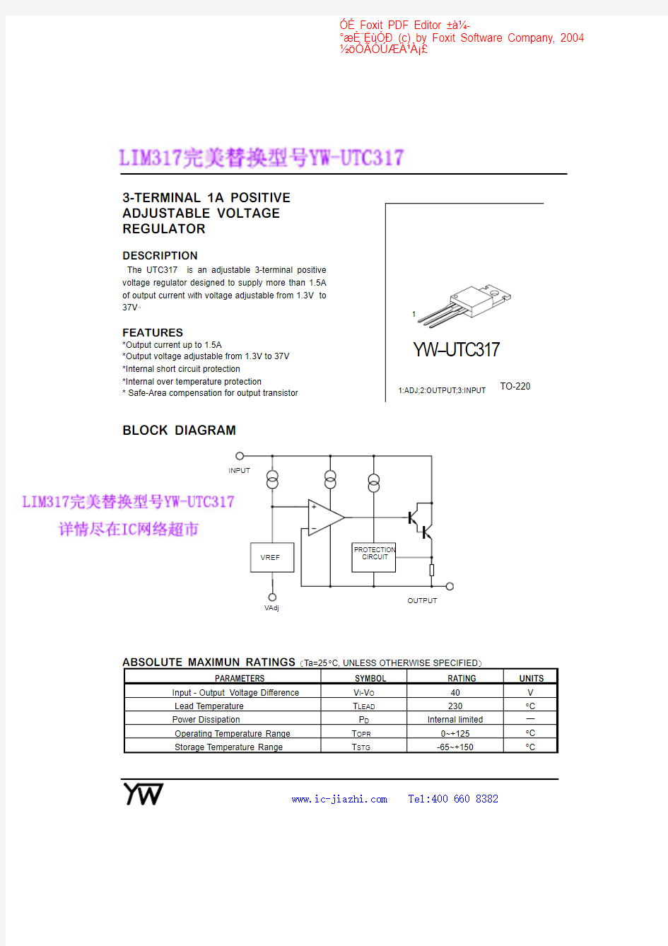
3-TERMINAL 1A POSITIVE ADJUSTABLE VOLTAGE REGULATOR
DESCRIPTION
The UTC317
is an adjustable 3-terminal positive
voltage regulator designed to supply more than 1.5A of output current with voltage adjustable from 1.3V to 37V
FEATURES
*Output current up to 1.5A
*Output voltage adjustable from 1.3V
to 37V *Internal short circuit protection
*Internal over temperature protection
*Safe-Area compensation for output transistor
TO-220
1
1:ADJ;2:OUTPUT;3:INPUT
BLOCK DIAGRAM
VAdj
ABSOLUTE MAXIMUN RATINGS
Ta=25°C,UNLESS OTHERWISE SPECIFIED
PARAMETERS
SYMBOL
RATING
UNITS
Input -Output Voltage Difference V I -V O 40V
Lead Temperature T LEAD 230°C
Power Dissipation
P D Internal limited
ü
Operating Temperature Range T OPR 0~+125°C Storage Temperature Range
T STG
-65~+150
°C
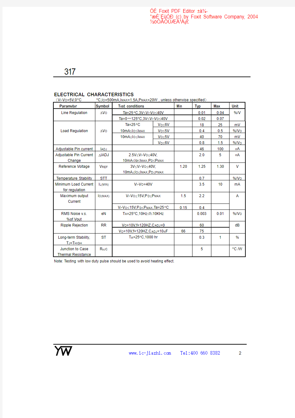
ELECTRICAL CHARACTERISTICS
V I-V O=5V,0°C Parameter Symbol Test conditions Min Typ Max Unit Line Regulation?V O Ta=25°C,3V≤V I-V O≤40V0.010.04%/V Ta=0ü125°C,3V≤V I-V O≤40V0.020.07 Ta=25°C V O≤6V1825mV Load Regulation?V O10mA≤I O≤I MAX V O≤5V0.40.5%/V O 10mA≤I O≤I MAX V O≤5V4070mV V O≤6V0.8 1.5%/V O Adjustable Pin current I ADJ46100μA Adjustable Pin Current Change ?IADJ 2.5V≤V I-V O≤40V, 10mA≤Io≤I MAX,P D≤P MAX 2.05μA Reference Voltage V REF3V≤V I-V O≤40V, 10mA≤I O≤I MAX,P D≤PMAX 1.20 1.25 1.30V Temperature Stability STT0.7%/V O Minimum Load Current for regulation I L(MIN)V I-V O=40V 3.510mA Maximum output Current I O(MAX)V I-V O≤15V,P D≤P MAX 1.5 2.2A V I-V O≤15V,P D≤P MAX,Ta=25°C0.150.4 RMS Noise v.s. %of Vout eN T A=25°C,10H Z≤f≤10KH Z0.0030.01%/V O Ripple Rejection RR V O=10V,f=120HZ,C ADJ=060dB V O=10V,f=120HZ,C ADJ=10μF6675 Long-term Stability, T J=T HIGH ST T A=25°C,1000hr0.31% Junction to Case Thermal Resistance RθJC5°C/W Note:Testing with low duty pulse should be used to avoid heating effect. 317 TYPICAL CHARACTERISTICS PERFORMANCE Temperature O u t p u t V o l t a g e D e v i a t i o n Fig.1.Load Regulation vs temperature -50 -250255075100125 3540 45 50 55 60 Fig.2Adjustment Current vs Temperature A d j u s t m e n t C u r r e n t Temperature Fig.3.Dropout Voltage vs Input-Temperature I n p u t -O u t p u t V o l t a g e D i f f e r e n c e R e f e r e n c e V o l t a g e Temperature TYPICAL APPLICATION CIRCUITS Fig.5Programmable voltage regulator Fig.6Regulator with On-off control Vo=1.25V*(1+R2/R1)+Iadj*R2 C1is required when regulator is located an appreciated distance from power supply.Co is needed to improve transient response. 317 Iomax=( Vref R1 )+Iadj= 1.25V R1 Iomin=( Vref R1+R2 )+Iadj= 1.25V R1+R2 5mA 317