Carbon-doped TiO2
Applied Catalysis B:Environmental 107 (2011) 128–134
Contents lists available at ScienceDirect
Applied Catalysis B:
Environmental
j o u r n a l h o m e p a g e :w w w.e l s e v i e r.c o m /l o c a t e /a p c a t
b
Carbon-doped TiO 2coating on multiwalled carbon nanotubes with higher visible light photocatalytic activity
Ye Cong a ,?,Xuanke Li a ,Yun Qin a ,Zhijun Dong a ,Guanming Yuan a ,Zhengwei Cui a ,Xiaojun Lai b
a Hubei Coal Conversion and New Carbon Materials Key Laboratory,Wuhan University of Science and Technology,Wuhan,Hubei 430081,China b
Institute of Particle Science and Engineering,School of Process,Environmental and Materials Engineering,University of Leeds,Leeds LS29JT,UK
a r t i c l e
i n f o
Article history:
Received 21March 2011
Received in revised form 26June 2011Accepted 3July 2011
Available online 13 July 2011
Keywords:
Carbon nanotubes Titanium dioxide Carbon-doping Photocatalysis Mechanism
a b s t r a c t
Carbon-doped titanium dioxide (TiO 2)coating on multiwalled carbon nanotubes (MWCNTs)was pre-pared by oxidation of titanium carbide (TiC)coated MWCNTs.The structure,morphology and surface chemistry states of the TiO 2coating on MWCNTs were characterized by XRD,SEM,HRTEM and XPS.The results suggest that the TiO 2coated MWCNTs keep the similar morphology and length with the pris-tine MWCNTs.The TiO 2coating,composed of homogeneous nanosized particles,contacts closely with MWCNTs via chemistry bond and Ti–O–C bonds are found.The visible light photocatalytic activity of the prepared photocatalyst was evaluated by decomposition of methylene blue aqueous solution.A prob-able mechanism of TiO 2and MWCNTs on the enhancement of visible light performance is proposed.It suggests that MWCNTs play key roles,which may act as a support,absorbent,photo-generated transfer station and carbon-doping source.
? 2011 Elsevier B.V. All rights reserved.
1.Introduction
Photocatalytic technology has attracted extensive attention for its cleaning,no second pollution and deep oxidation–reduction reaction under ambient temperature.A number of research top-ics in photocatalysis have emerged and offered the potentials for commercial development and environmental protection,such as splitting water to produce hydrogen fuel and decomposing [1,2],selective synthesis of organic compounds [3],removal of organic or inorganic pollutants [4,5],solar cells and sensors [6].Although titanium dioxide is widely accepted as the most promising pho-tocatalyst for its higher photocatalytic activity,chemical stability,nontoxicity and low price [7,8],there are still some dif?culties hampering its wide application because of its low quantum yield associated with the rapid recombination of photogenerated elec-trons and holes,low adsorption capacity and dif?cult recovery of photocatalyst.
Since being reported in 1991,carbon nanotubes have received much interest for their unique electrical property and large speci?c surface area and hence been used as a representative system for the study of electronic transport at the nanoscale [9,10].The physical properties of high mechanical strength and large speci?c surface area,hollow and layered structures of carbon nanotubes make car-bon nanotubes to be a good supporting material for catalysts.In
?Corresponding author.Tel.:+862786556906;fax:+862786556906.E-mail address:congye626@https://www.sodocs.net/doc/b15175719.html, (Y.Cong).
addition,carbon nanotubes show higher electron conducting abil-ity and higher adsorption capacity,which means they can act as promising materials in environmental cleaning.
Combining the ef?cient photocatalytic activity of titania with the excellent adsorption and charge transfer abilities of carbon nanotubes,the composites of titania and carbon nanotubes have been considered as more advanced candidate of photocatalyst.The common approaches to synthesize titania and carbon nanotube composite structure include sol–gel method [11,12],chemical vapor deposition (CVD)[13,14],electrospinning [15],sputtering deposition [16],and so on [17].Various different structural forms of titania–carbon nanotubes photocatalysts have been prepared,such as TiO 2nanoparticles on MWCNTs [18],TiO 2layer coating on aligned MWCNT arrays [19],carbon nanotubes incorporating into the TiO 2?lm [20],and TiO 2layer coating on MWCNTs [21].
In this work,TiO 2coated multiwalled carbon nanotubes with uniform and ?ne well-dispersed TiO 2coating were prepared via an approach including two step reactions:an intermediate product formation of TiC coated MWCNTs by molten salt method followed by the ?nal product formation of TiO 2coated MWCNTs by control-lable oxidation process.Because the TiO 2coating on MWCNTs is produced from oxidation of TiC,the coating is intimately contacted with the MWCNT support and is expected to form chemical bonds with the MWCNT substrate.It is bene?cial for the enhancement of the stability and the transmission of photo-generated electron between the MWCNTs and the conduction band of TiO 2.Further-more,carbon-doped TiO 2comes into being through the diffusion of carbon to the surface and interface of TiO 2and MWCNTs,which has
0926-3373/$–see front matter ? 2011 Elsevier B.V. All rights reserved.doi:10.1016/j.apcatb.2011.07.005
Y.Cong et al./Applied Catalysis B:Environmental107 (2011) 128–134129
been proved favorable for improving the photocatalytic activity. The photocatalytic activities of the prepared TiO2coated MWC-NTs were evaluated by degradation of methylene blue under visible light irradiation.
2.Experimental
2.1.Materials
The multi-walled carbon nanotubes(MWCNTs with purity >95%;diameter>50nm;length10–20?m)were provided by Chengdu Organic Chemicals Co.Ltd.,Chinese Academy of Sciences. Titanium powder,with?neness about300meshes and purity above 99.9%,was purchased from Beijing Mountain Technical Co.Ltd., China.Methylene blue(MB,analytical grade)was purchased from Sinopharm Chemical Reagent Co.Ltd.,China,and used without fur-ther puri?cation.All other chemicals were of analytical grade.
2.2.Preparation of carbon-doped TiO2coating on MWCNTs
The TiO2coated MWCNT photocatalysts were synthesized by a two-step approach.First,an intermediate product of TiC coated MWCNTs was prepared using molten salt method,based on our previous work[22,23].The MWCNTs were used as a reaction tem-plate and carbon source,and titanium powder as the titanium source.The titanium powder was added into a molten salt sys-tem composed of anhydrous KCl and LiCl with the appropriate ratio of the salt mixture.The mixture was completely grinded.The MWCNTs were dispersed in isopropanol by ultrasonic vibration for 15min and homogeneously mixed with the above mixture and then dried for several hours in an oven at120?C.The molar ratio of MWC-NTs to titanium powder was3:1.This mixture was then placed in a covered alumina crucible and heat-treated at800?C for3h under a?owing argon atmosphere to initiate the reaction.After cooling, the crucible was repeatedly washed in water to remove the salts. The remaining product was dried at80?C for5h to receive the intermediate product of TiC coated MWCNTs.Finally,the TiC coated MWCNTs were controllably oxidized under?owing air at different temperatures for5h to obtain the carbon-doped TiO2coating on MWCNTs.
2.3.Structural characterization
The crystal phases of the samples were characterized by X-ray diffraction(XRD)performed on a Philips X’Pert MPD Pro X-ray diffractometer with Cu K?radiation( =1.54056?A).The mor-phology of the photocatalyst was analyzed using a?eld-emission scanning electron microscope(FE-SEM:Nova400Nano)operating at30kV after being sputtered with gold.The transmission electron microscopy(TEM)and selected area electron diffraction(SAED) were used to probe the product microstructure and elemental composition on a Philips CM200?eld emission gun transmission electron microscope(FEG-TEM)operating at197kV.The surface properties of the photocatalyst were investigated using X-ray pho-toelectron spectrum analysis(XPS)on VG Multilab2000X-ray photoelectron spectroscopy with Mg K?X-rays(h =1253.6eV) radiation operated at300W.The shift of the binding energy due to the relative surface charging was corrected using the C1s level at284.6eV as an internal standard.
2.4.Photocatalytic activity measurement
The photocatalytic activity was evaluated by measuring the decolorization rate of methylene blue aqueous solution(MB,with a concentration of20mg/L)in a home-made photoreactor
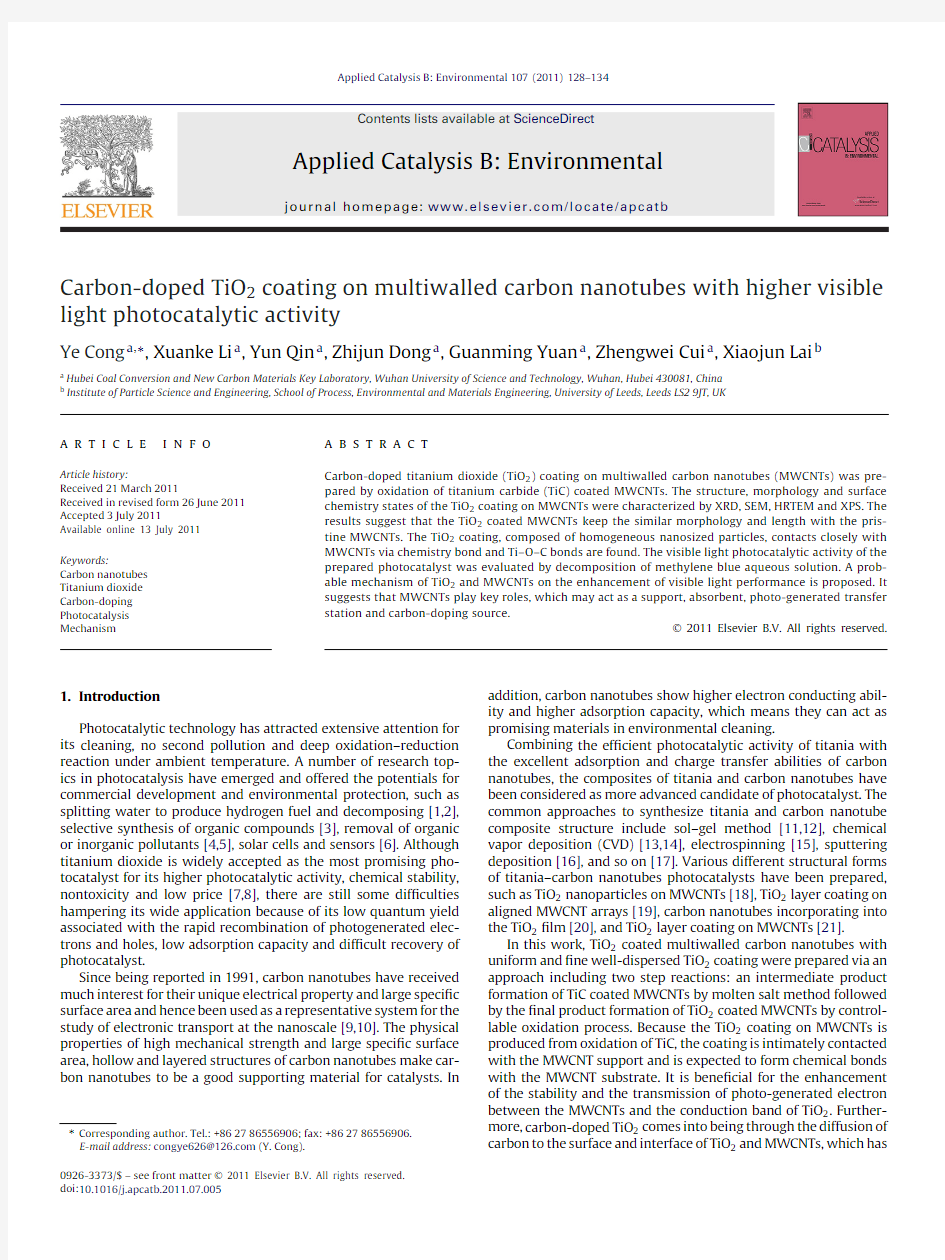
under Fig.1.XRD patterns of(a)pristine MWCNTs;(b)TiC coated MWCNTs prepared at 800?C for3h in molten salt system.
visible light irradiation at ambient temperature.0.12g of the pre-pared photocatalyst and80mL of MB aqueous solution were placed in a quartz tube with continuous magnetic stirring.A500W halo-gen lamp was used as the visible light source,surrounding with cool water at the outer wall through a quartz jacket.The short-wavelength components( <420nm)of the light were cut off using a glass optical?lter.Samples were withdrawn periodically from the reactor,centrifuged and then?ltered using a0.22?m mem-brane?lter to remove the particles.The concentration of MB during the photocatalytic degradation was determined from the?ltered absorbance at the characteristic wavelength of MB by a UV-3010 Ultraviolet–Visible spectrometer according to the calibration curve. The decolorization rate(á,%)could be calculated as the following equation:
á(%)=
1?
c
c0
×100=
1?
A
A0
×100
where c0and A0are the concentration and absorbance of MB prior to irradiation,respectively,while c and A are the concentration and absorbance of MB at a certain irradiation time,respectively.
3.Results and discussion
Fig.1shows the XRD patterns of the pristine MWCNTs and the intermediate product TiC coated MWCNTs which were prepared in a KCl–LiCl molten salt medium at800?C for3h.There is a sharp and intense peak at about26.3?(shown in Fig.1a),which is correspond-ing to the(002)re?ection peak of MWCNTs;while other weak and broad peaks at about42.8?,44.5?and54.2?are corresponding to the (100),(101)and(004)re?ection peaks of MWCNTs,respectively. After molten salt reaction,the(002)re?ection peak of MWCNTs at26.3?is remarkably weakened due to the formation of titanium carbide via the uncompleted reaction of MWCNTs with titanium powder with the molar ratio of3:1in the molten salt medium. There are?ve sharp peaks at about36.0?,41.8?,60.5?,72.4?and 76.3?corresponding to diffractions from the(111),(200),(220), (311)and(222)crystal planes of a face-centered cubic TiC phase, respectively.It suggests that the prepared intermediate product has formed perfect crystalline TiC coating and still retains part of MWCNTs as a core.
The oxidation temperature was chosen based on the TG–DSC curves of MWCNTs(not shown).The evident weight loss com-menced at about475?C for MWCNTs in?owing air due to the oxidation of MWCNTs.Therefore,the oxidation conversion of TiC
130Y.Cong et al./Applied Catalysis B:Environmental 107 (2011) 128–
134
Fig.2.(A)XRD patterns of the TiO 2coated MWCNT composite obtained by oxidizing TiC coated MWCNTs at different temperatures for 5h:(a)200?C;(b)300?C;(c)350?C;(d)400?C and (e)450?C;(B)?tting curve of (b)300?C.
coated MWCNTs into TiO 2coated MWCNTs must be carried out below 475?C if we expect to retain part of MWCNTs as a support of the ?nal photocatalyst.The XRD patterns of the obtained TiO 2coated MWCNTs obtained by oxidizing intermediate product TiC coated MWCNTs at different temperatures are presented in Fig.2.The product oxidized at 200?C (Fig.2a)shows the similar XRD pat-terns with TiC coated MWCNTs (Fig.1a).There is one diffraction peak at 26.3?attributed to MWCNTs and ?ve other diffraction peaks attributed to the cubic phase of TiC.No titania diffraction peak appears due to the lower oxidation temperature.At temperature
300?C,the intensities of TiC phase peaks remarkably decrease and two peaks at 72.4?and 76.3?almost disappear.However,there are several new peaks at 25.3?,37.8?,48.0?,53.9?,55.1?and 62.7?cor-responding to the diffraction peak of (101),(004),(200),(105),(211)and (204)crystal planes of anatase TiO 2,respectively.It is noted that the peak at about 25.3?is asymmetric,which can be ?tted into two peaks at 25.3?and 26.3?(e.g.Fig.2B)attributed to anatase TiO 2(101)and MWCNT (002)planes,respectively.The peak of (002)of MWCNTs is overlapped by (101)of TiO 2.It mani-fests the existence of a ternary composite of MWCNTs–TiC–TiO 2
.
Fig.3.FE-SEM images of (a)MWCNTs;(b)TiC coated MWCNTs;(c)TiO 2coated MWCNTs prepared by oxidizing at 300?C and (d)400?C for 5h.
Y.Cong et al./Applied Catalysis B:Environmental107 (2011) 128–134
131
Fig.4.TEM images of(a)the TiC coated MWCNTs and(b–d)the TiO2coated MWCNTs;the inset in(a)is an SAED pattern(indexed to cubic TiC and graphite)from the?bres shown in(a);the inset in(c)is an SAED pattern(indexed to tetragonal anatase TiO2and graphite)from the?bres shown in(c).
With the further increase of oxidizing temperature,the diffrac-tion peak intensities of titanium dioxide gradually increase and the more diffraction peaks can be seen,whereas the diffraction peaks of titanium carbide almost disappear.This indicates that the integrity of crystal structure of anatase TiO2was enhanced.However,with the temperature increase to450?C,a peak at about27.5?corre-sponding to rutile TiO2emerges,which means the transformation of crystalline phase.Therefore,by controlling the oxidizing tem-perature within some desirable range,different crystal phase of composites can be obtained.
Fig.3displays the FE-SEM images of the pristine MWCNTs,the intermediate product TiC coated MWCNTs and the?nal product TiO2coated MWCNTs oxidizing at300?C and400?C.It can be seen that the TiC coated MWCNTs and the TiO2coated MWCNTs keep the similar morphology and length with the pristine MWCNTs.How-ever,the nanotube diameters of the products are signi?cantly larger than those of the pristine MWCNTs.The TiC and TiO2coatings on the surface of MWCNTs are composed of uniform nanosized particles. Furthermore,in comparison to the TiO2coated MWCNTs prepared by the oxidation of TiC coated MWCNTs at300?C for5h,the?ne particles of TiO2coating on MWCNTs prepared by400?C oxidation show a more compact and uniform morphology,and larger particle diameter.
The morphology and microstructure of the TiC coated MWC-NTs and the TiO2coated MWCNTs oxidizing at400?C for5h are further characterized by transmission electron microscopy(TEM) and selected area electron diffraction(SAED).Fig.4a shows the TEM images of the TiC coated MWCNTs,the morphology of which is sim-ilar with that of the pristine MWCNTs.The SAED pattern of the TiC coated MWCNTs is also shown in Fig.4a(inset image),which dis-plays diffraction rings indexable to the(111),(200),(220),(311) and(222)planes of cubic TiC and the(002)and(100)planes of graphite(MWCNTs).The relative intensities of the rings in the SAED pattern are similar to the standard XRD intensities for bulk cubic TiC and graphite.Fig.4b–d shows the representative TEM images of the TiO2coated MWCNTs oxidizing at400?C for5h.It can be seen that after oxidation process the diameters of TiO2coated MWCNT ?bres(Fig.4b)are clearly larger than those of TiC coated MWCNTs (Fig.4a).Compact TiO2nanoparticles uniformly cover on the sur-face of the MWCNTs(Fig.4b and c),which is consistent with the results of the SEM measurement.There are no clear boundary and vacant space between the TiO2coating and the MWCNT substrate. The nanoparticles covered on the MWCNTs show clear crystal lat-tice fringes(Fig.4d).The crystal interplanar spacing(d-spacing) of the nanoparticle is about0.35nm,which is corresponding to the(101)planes of anatase TiO2.Furthermore,the(101)crystal planes of anatase show different orientation,which means no spe-cial relationship of crystal orientation between the titania coating and MWCNTs[13].The other crystal interplanar spacing is about 0.34nm,which is attributed to the(002)planes of MWCNTs.The
132Y.Cong et al./Applied Catalysis B:Environmental 107 (2011) 128–
134
Fig.5.XPS survey spectra for the surface of TiO 2coated MWCNTs:(a)general XPS spectrum;(b–d)XPS spectra of individual lines of C1s,O1s and Ti2p measured at a high resolution,respectively.
crystalline nature of the composite can be further illustrated by the SAED patterns (inset image of Fig.4c).This SAED pattern can be indexed to (101),(004),(200),(105),(211)and (204)crystal planes of tetragonal anatase TiO 2as well as (002)and (100)planes of graphite (MWCNTs).The wide and bright diffraction ring near to the diffraction pattern center can be indexed to the (002)crystal plane of graphite (MWCNTs)and (101)crystal plane of anatase TiO 2because of the close (002)d -spacing (0.34nm)of graphite and (101)d -spacing (0.35nm)of the anatase TiO 2.The relative intensities of the rings in the SAED pattern are also similar to the XRD intensities for the TiO 2coated MWCNTs.The results of TEM (shown in Fig.4c and d)and SAED con?rm that the composite is mainly composed of MWCNT core and anatase TiO 2coating.
X-ray photoelectron spectrum (XPS)is a powerful and valuable technique for the investigation of electron structure to characterize the valance states and the chemical environment of atom on the surface of materials.The sample for XPS is TiO 2coated MWCNTs obtained by oxidizing at 400?C for 5h.The general XPS spectrum (Fig.5a)shows that the main elements on the surface of the product are titanium,oxygen and carbon.Fig.5b–d shows the XPS spectra of individual lines of C1s,O1s and Ti2p measured at a high resolution,respectively.The high resolution of C1s XPS spectrum in Fig.5b can be ?tted into three peaks.The major peak with the binding energy of 284.6eV is attributed to graphitic carbon (C C bond)and C–C bond from MWCNTs.The peaks at 286.2eV are attributed to C–O bond;while the broad peak centered at 288.2eV is ascribed to C O or COO bonds [19,24].No peak at 281.0eV appears correspond-ing to C–Ti bond,which means no TiC existence on the surface of MWCNTs.It indicates that the TiC coating has been converted into TiO 2coating on the surface after 400?C oxidation.The O1s spectrum (shown in Fig.5c)presents four chemical states of oxy-gen.The strongest peak at about 530.6eV is corresponding to the Ti–O bond of TiO 2,which means that the chemical state of oxy-gen is main lattice oxygen in titania.The peaks at 531.6,532.6and 534.0eV are assigned to O–H bond (hydroxyl group),C–O bond and water molecules adsorbed on the surface TiO https://www.sodocs.net/doc/b15175719.html,bining the XPS spectra and the ?tting curves of C1s and O1s suggests that Ti–O–C bond presents,which is formed from the close con-tact and reaction of TiO 2nanoparticles with MWCNTs.Therefore,in the prepared TiO 2coated MWCNT product,carbon-doped TiO 2presents,which has been testi?ed bene?cial to improve the vis-ible light photocatalytic activity of titania.As can be seen from Fig.5d the Ti2p spectrum,Ti2p1/2and Ti2p3/2spin–orbital split-ting photoelectrons are located at binding energies of 465.1and 459.4eV,respectively,which are slightly shifting towards higher binding energy in comparison to those of the pure bulk anatase [24].This indicates that the chemical environment of Ti in TiO 2coated MWCNTs is different from that of pure anatase,which is probably due to the strong interaction between TiO 2nanoparticles and the MWCNTs and the formation of Ti–O–C bond.
The photocatalytic activity of photocatalyst was evaluated by degradation of 20mg/L methylene blue (MB)aqueous solutions using visible light irradiation source.The decolorization rate was calculated according to the absorbance change at 664nm.Several photocatalysts were chosen as model to compare the photocat-alytic ef?ciency.The TiO 2nano?bres in Fig.6b were obtained by the oxidation conversion under ?owing air atmosphere at 400?C for 5h of the TiC nano?bres prepared via molten salt reaction from the mixture of MWCNTs and titanium powders with molar ratio 1:1.Carbon-doped TiO 2coating on MWCNTs in Fig.6e was pro-duced from the oxidation of TiC coated MWCNTs with a C/Ti molar ratio 3:1in molten salt system and oxidation under ?owing air at 400?C for 5h.In addition,the P25and the simple mixture of P25and MWCNTs were also used as photocatalysts for comparison.Fig.6shows the decolorization rate of MB for P25,the mixture of P25,TiO 2nano?bres,the mixture of TiO 2nano?bres and MWCNTs,and
Y.Cong et al./Applied Catalysis B:Environmental107 (2011) 128–134
133
Fig.6.Decolorization rate of MB on(a)P25,(b)TiO2nano?bres,(c)mixture of P25 and MWCNTs,(d)mixture of TiO2nano?bres and MWCNTs,and(e)carbon-doped TiO2coating on MWCNTs under visible light irradiation(shown in the solid line);and decolorization rate of MB on(f)TiO2nano?bres and(g)carbon-doped TiO2coating on MWCNTs without irradiation(shown in the dotted line).
carbon-doped TiO2coating on MWCNTs.Firstly,the carbon-doped TiO2coating on MWCNTs shows higher adsorption rate compared with the nano?bres without irradiation,which is probably due to the large speci?c surface area and hollow structures of TiO2coated MWCNTs.It can also be seen that photocatalytic activity of the pre-pared TiO2nano?bres(Fig.6b)is obviously higher than that of P25 (Fig.6a),which is probably due to the?bre structure and higher surface area of the prepared TiO2.Furthermore,in comparison to single TiO2nano?bre,the decolorization rate of the mixture of TiO2nano?bre and MWCNTs is enhanced,which indicates that the adsorption effect of MWCNTs is one of the main effects in removal of MB solution.Moreover,it must be worthy of notice that the carbon-doped TiO2coating on MWCNTs shows a better decolorization rate to compare with the simple mixture of TiO2nano?bres and MWC-NTs.It suggests that the connection between TiO2and MWCNTs would play an important role for photocatalytic activity.
Based on the results of the structure characterizations and the visible light photocatalytic activity tests of the prepared photocat-alysts,a probable synergistic effect between TiO2and MWCNTs on the enhancement of photocatalytic activity is proposed(shown in Fig.7).First,stronger adsorption on photocatalyst for MB will be achieved by the incorporation of MWCNTs,due to their large speci?c surface area,hollow and layered structures.Second, the MWCNTs can act as effective electron transfer station since they exhibit high electrical conductivity and high electron storage capacity.MWCNTs manifest higher capture electron ability and can prompt electron transfer from the conduction band of TiO2towards the MWCNT surface due to their lower Fermi level.Therefore,a Schottky barrier is capable of forming at the interface between the MWCNTs and TiO2.The photo-generated electrons may move freely towards the MWCNT surface,thus the left holes may move to the valence band of TiO2since MWCNTs show high electrical con-ductivity and electron storage capacity[25,26].This process can inhibit the recombination of photo-generated electrons and holes, which is favorable for improvement of photocatalytic activity.Fur-thermore,because of the strong interaction and intimate contact between TiO2nanoparticles and the MWCNTs,the transmission stability of photo-generated electron between the MWCNTs and the conduction band of TiO2is enhanced.Meanwhile,carbon dop-ing is found for the presence of the Ti–O–C bonds as discussed in XPS spectra.It has been extensively approved that carbon doping would introduce a mid band-gap state close to the TiO2valence
bond Fig.7.Proposed mechanism of synergistic enhancement of visible light photocat-alytic activity in carbon-doped TiO2coating on MWCNTs.
and extends light absorption to longer wavelength region[27,28]. Therefore,the prepared carbon-doped TiO2coating on MWCNTs shows a higher visible light photocatalytic activity.
4.Conclusions
Uniform and?ne well-dispersed carbon-doped TiO2coating on multiwalled carbon nanotubes has been successfully prepared via an oxidation conversion of TiC coated MWCNT approach.The struc-ture,surface morphology and surface element chemical states have been investigated.The oxidation temperature plays a key role for the control of the phase composition of the?nal product.The crystal phase composition varies from TiC–MWCNTs,TiO2–TiC–MWCNTs, TiO2–MWCNTs to TiO2with the temperature increasing.Uniform and?ne well-dispersed TiC and/or TiO2coatings are formed on the surface of MWCNT template.The prepared products keep the similar morphology and length with the pristine MWCNTs.The TiO2coating contacts closely with MWCNTs via chemistry bond, so the coating is not easy to drop off from the MWCNT support and can also provide ef?cient transfer of charge and/or adsorbed react-ing species.Ti–O–C bonds are formed in the prepared TiO2coated MWCNT photocatalyst,which manifests carbon doping existed in the structure.The visible light photocatalytic activities were tested using the decolorization of MB in model aqueous solution.Further-more,a probable synergistic effect of TiO2and MWCNTs on the enhancement of visible light performance is proposed.MWCNTs may act as support,absorbent,photo-generated transfer station and carbon-doping source to narrow the band gap of TiO2. Acknowledgment
This project is supported by National Nature Science Foundation of China(No.20803054).
References
[1]T.Takata,K.Domen,J.Phys.Chem.C113(2009)19386–19388.
[2]G.K.Mor,K.Shankar,M.Paulose,O.K.Varghese,C.A.Grimes,Nano Lett.5(2005)
191–195.
[3]M.Morishita,Y.Shiraishi,T.Hirai,J.Phys.Chem.B110(2006)17898–17905.
[4]G.Li,D.Zhang,J.C.Yu,M.K.H.Leung,Environ.Sci.Technol.44(2010)4276–4281.
134Y.Cong et al./Applied Catalysis B:Environmental107 (2011) 128–134
[5]Y.Cong,J.Zhang, F.Chen,M.Anpo, D.He,J.Phys.Chem.C111(2007)
10618–10623.
[6]G.K.Mor,K.Shankar,M.Paulose,O.K.Varghese,C.A.Grimes,Nano Lett.6(2006)
215–218.
[7]Y.Cong,J.Zhang,F.Chen,M.Anpo,J.Phys.Chem.C111(2007)6976–6982.
[8]J.S.Im,S.M.Yun,Y.S.Lee,J.Colloid Interface Sci.336(2009)183–188.
[9]S.Iijima,Nature354(1991)56–58.
[10]P.Sundqvist,F.J.Garcia-Vidal,F.Flores,M.Moreno-Moreno,C.Gómez-Navarro,
J.S.Bunch,J.Gómez-Herrero,Nano Lett.7(2007)2568–2573.
[11]S.Wang,L.J.Ji,B.Wu,Q.Gong,Y.Zhu,J.Liang,Appl.Surf.Sci.255(2008)
3263–3266.
[12]W.D.Wang,P.Serp,J.L.Faria,Appl.Catal.B:Environ.56(2005)305–312.
[13]H.Yu,X.Quan,S.Chen,H.Zhao,Y.Zhang,J.Photochem.Photobiol.A:Chem.
200(2008)301–306.
[14]H.Yu,X.Quan,S.Chen,H.Zhao,J.Phys.Chem.C111(2007)12987–12991.
[15]S.Aryal,C.K.Kim,K.W.Kim,M.S.Khil,H.Y.Kim,Mater.Sci.Eng.C28(2008)
75–79.
[16]B.Liu,X.Zhao,Q.Zhao,C.Li,X.He,Mater.Chem.Phys.90(2005)207–212.
[17]M.L.Chen,F.J.Zhang,W.C.Oh,New Carbon Mater.24(2009)159–166.[18]Y.Yao,G.Li,S.Ciston,R.M.Lueptow,K.A.Gray,Environ.Sci.Technol.42(2008)
4952–4957.
[19]O.Akhavan,M.Abdolahad,Y.Abdi,S.Mohajerzadeh,Carbon47(2009)
3280–3287.
[20]G.Jiang,Z.Lin,L.Zhu,Y.Ding,H.Tang,Carbon48(2010)3369–3375.
[21]A.Jitianu,T.Cacciaguerra,R.Benoit,S.Delpeux,F.Béguin,S.Bonnamy,Carbon
42(2004)1147–1151.
[22]X.Li,A.Westwood,A.Brown,R.Brydson,B.Rand,Carbon47(2009)201–208.
[23]X.Li,Z.Dong,A.Westwood,A.Brown,S.Zhang,R.Brydson,N.Li,B.Rand,Carbon
46(2008)305–309.
[24]G.An,W.Ma,Z.Sun,Z.Liu,B.Han,S.Miao,Z.Miao,K.Ding,Carbon45(2007)
1795–1801.
[25]K.Woan,G.Pyrgiotakis,W.Sigmund,Adv.Mater.21(2009)2233–2239.
[26]Y.Chen,J.C.Crittenden,S.Hackney,L.Sutter,D.W.Hand,Environ.Sci.Technol.
39(2005)1201–1208.
[27]K.Yang,Y.Dai, B.Huang,M.H.Whangbo,J.Phys.Chem.C113(2009)
2624–2629.
[28]M.Lim,Y.Zhou,B.Wood,Y.Guo,L.Wang,V.Rudolph,G.Lu,J.Phys.Chem.C
112(2008)19655–19661.
锐钛型二氧化钛与金红石型二氧化钛的区分
1、(锐钛型二氧化钛与金红石型二氧化钛)的区分 1.1 方法 利用X射线衍射仪得到XRD图谱进行分析 1.2用到的仪器 X射线衍射仪 X射线产生原理: 高速运动的电子与物体碰撞时,发生能量转换,电子的运动受阻失去动能,其中一小部分(1%左右)能量转变为X射线,而绝大部分(99%左右)能量转变成热能使物体温度升高 1.2.1 X射线管的结构 阴极:又称灯丝(钨丝),通电加热后便能释放出热辐射电子。 阳极:又称靶,通常由纯金属制成(Cr,Fe,Co,Ni,Cu,Mo,Ag, W等),使电子突然减速并发射X射线。阳极需要水强制冷却。 窗口:是X射线射出的通道,维持管内高真空,对X射线吸收 较少,如金属铍、含铍玻璃、薄云母片 X射线管中心焦点
在X射线衍射中,总希望有较小的焦点(提高分辨率)和较强的X射线强度(缩短爆光时间)。 一般采用在与靶面成一定角度的位置接受X射线,这样可以达到焦点缩小,X射线相应增强的目的。 1.2.2 X射线特点
1.2.3理论基础:布拉格方程 1.2.4具体方法 用X射线衍射分析法中的粉末法来分析两种结构。 只有满足Bragg方程,才能产生衍射现象,因此用粉末法对测定的晶体样品,不改变λ,要连续改变θ。: ?用单色的X射线照射多晶体试样,利用晶体的不同取向来改变θ,以满足 Bragg方程。试样要求:粉末,块状晶体。 ?特点:试样容易获得,衍射花样反映晶体的全面信息。
粉末法:由于多晶体由无数取向无规的单晶组成,相当于单晶绕所有取向的轴转动,晶体内某等同晶面族{HKL}的倒易点,形成-相应倒易矢量gHKL为半径的倒易球。一系列的倒易球与反射球相交,其交集是一系列园,则相应的衍射线束分布于以样品为中心、入射方向为轴、上述交线园为底的园锥面上。 1.2.5 两者结构分析 晶胞结构的不同 金红石型二氧化钛及锐钛型二氧化钛结晶类型均为正方结晶,前者为R型,后者为A型。金红石型二氧化钛晶格结构致密,比较稳定,光化学活性小,因而耐久性由于锐钛型二氧化钛。另外,金红石型二氧化钛晶体结构是细长的成对的孪生晶体,每个金红石晶胞含有2个二氧化钛分子,以两个棱相连,这比锐钛型二氧化钛八面体的形式体积更小、结构更密,因而硬度和密度增大,介电常数和导热性增加,所以耐候性好,不易粉化 (a)金红石型 (b)锐钛型 金红石型和锐钛型晶胞中TiO2分子数分别是2和4。晶胞参数分别是:金红石型a:4.593A,c=2.959A;锐钛型a=3.784A,c=9.515^。金红石型二氧化钛比锐钛型二氧化钛稳定而致密,有较高的硬度、密度、介电常数及折射率,其遮
环境与材料科学技术的前沿进展刘艳艳武汉理工大学资源与环境工程
环境与材料科学技术的前沿进展 刘艳艳武汉理工大学资源与环境工程学院 资源与环境已成为当今世界发展的主题。经济与资源、环境之间的和谐发展日益广泛受到关注。如何合理利用资源、保护环境,同时促进经济的增长,这对相应学科的科学与技术提出了高要求,也已成为全球化的重要议题。2015环境与材料科学技术学术研讨会在武汉理工大学资源与环境工程学院院长宋少先教授的主持下拉开帷幕。出席开幕式的人员包括圣路易斯波多西自治大学校长ManuelVilla、武汉理工大学副校长康灿华、圣路易斯波多西自治大学物理研究所所长JoséLuisArauzLara、武汉理工大学新材料研究所所长余家国教授等,还包括武汉理工大学资环学院、理学院、化生学院、材料复合新技术国家实验室等单位百余名师生参加。研讨会主题是“环境与材料科学技术”,会议旨在为中墨两国合作搭建潜在的平台,为环境、材料、能源等多方领域交流最新研究成果提供一个交流的机会。研讨会主题围绕环境、材料、能源、地理空间科学与技术等领域进行了交流,包括1场大会报告与4组分会场报告,双方与会代表共进行37场次报告,展示了双方各自最新研究成果,探讨了环境、材料与能源等领域的发展趋势,为日后合作发展提供了机会。本研讨会获得了中国教育部、武汉理工大学以及圣路易斯波多西自治大学的大力支持。武汉理工大学康灿华副校长在研讨会开幕式上发言,希望利用本次机会充分展示该校在环境与材料科学技术领域的研究成果和特色,推动该校在该领域学科建设的发展并提升国际影响。ManuelVilla校长介绍了圣路易斯波多西自治大学的学校历史、学科结构及对外合作项目,希望两校在科研合作与学生交流等方面开展深入合作,为双方优秀学者和学生搭建良好的学术交流平台。武汉理工大学余家国教授在大会报告中介绍了用于生产太阳能燃料的石墨烯光催化材料的研究进展与发展趋势。利用太阳能转化制备太阳能燃料目前被认为是解决未来全球能源与环境问题的主要策略之一。其中利用光催化水产氢和还原二氧化碳制甲烷已经成为利用太阳光制备太阳能燃料的重要且有前景的方法,可以实现清洁、经济以及再生等生产。通常基于TiO2光催化产氢强烈依赖于触媒类型与数量,这是因为仅有TiO2不具备很高的光催化性能,需要添加Pt作为触媒,这样才能增强TiO2的光催化产氢性能,然而Pt更是稀有且昂贵的材料。因此,便宜且来源丰富的材料便成了触媒的另外选择。比如基于石墨烯的纳米复合材料作为光催化剂具备增强光催化产氢和二氧化碳还原的能力,能将太阳能转化成化学能。余家国教授对在基于石墨烯的纳米复合材料在光催化产氢和二氧化碳还原方面的设计与制造研究成果进行了介绍与分享。 圣路易斯波多西自治大学的MagdalenoMedi-na-Noyola教授作了题为“StructuralRelaxiationandAgingofGlassesandPhysicalGels:aNon-equilibriumStatisticalThermodyn amicTheory的大会报告。有一项关于非均衡液体不可逆过程的非均衡统计热力学理论被用来表述淬火液体结构与动力学的非稳态演变,该理论提出一个方案:演变时间是一个基础的变量。该方案为类玻璃材料在高填充率下的老化行为以及低密度的类凝胶材料的形成过程,方案设计符合通用情况,也符合各系统下的分子内作用过程。比如硬体系和Lennard-Jones简单液体等具体模型体系都能很好地解释这个预计方案。其定性定量准确度可以通过对比模拟和实验结果进行评估。武汉理工大学资源与环境工程学院张一敏教授作了题为“VanadiumExtractionfromVanadium-bearingCarbonaceousShaleinChina”的大会报告。钒作为
石墨烯及石墨烯光催化复合材料简介
石墨烯及石墨烯光催化复合材料简介 1.1 前言 碳材料是地球上最普遍也是一类具有无限发展前景的材料,从无定形的碳黑到晶体结构的天然层状石墨;从零维纳米结构的富勒烯到二维结构的石墨烯,近几十年来,碳纳米材料一直备受关注。而三维网状结构的石墨烯自组装水凝胶的发现[1],不仅极大地充实了碳材料家族,为新材料和凝聚态领域提供了新的增长点,而且由于其所具有的特殊纳米结构和性能,使得石墨烯无论是在理论上还是实验研究方面都已展现出了重大的科学意义和应用价值.从而为碳基材料的研究提供了新的目标和方向。 从石墨发现至今,关于石墨烯的研究已经铺满各种期刊杂志,此外,人们对石墨烯衍生物也进行了深入研究,如氧化石墨烯、石墨烯纳米带、石墨烷、磁性石墨烯衍生物等。其中对氧化石墨烯和石墨烯纳米带的研究更为深入。氧化石墨烯是单一的碳原子层,可以随时在横向尺寸上扩展到数十微米,因此,其结构跨越了一般化学和材料科学的典型尺度。氧化石墨烯可视为一种非传统型态的软性材料,具有聚合物、胶体、薄膜,以及两性分子的特性。由于它在水中具有优越的分散性,长久以来被视为亲水性物质,然而,相关实验结果显示,氧化石墨烯实际上具有两亲性,从石墨烯薄片边缘到中央呈现亲水至疏水的性质分布。因此,氧化石墨烯可如同界面活性剂一般存在界面,并降低界面间的能量。根据不同的碳取材来源和不同的结构,石墨烯纳米带有不同的特性,有些有金属的性质,有的具有半导体性能,从而也使得石墨烯纳米带成为未来半导体候选材料。此外,在挖掘石墨烯潜在的性能和应用方面,石墨烯的复合材料也受到了极大的关注,并且这类复合材料已在生物医学、能量储存、液晶器件、传感材料、电子器件、催化剂等领域显示出了优异的性能和潜在的应用。 总之,不断发现新的性质、衍生物、复合材料以及功能器件,极大地丰富了石墨烯的研究方向、开拓了人们的视野、拓展了石墨烯的应用领域,使得基于石墨烯的材料成为了一个充满魅力与无限可能的研究对象。
金红石型纳米二氧化钛制备中的若干影响因素
第31卷第4期 2004年北京化工大学学报 JOURNAL OF BEI J IN G UN IV ERSIT Y OF CHEMICAL TECHNOLO GY Vol.31,No.4 2004 金红石型纳米二氧化钛制备中的若干影响因素 侯 强 郭 奋 (北京化工大学教育部超重力工程研究中心,北京 100029) 摘 要:实验以TiCl 4为原料,采用液相沉积法在低温条件下直接制备了金红石型纳米二氧化钛。重点研究了反应物浓度、温度、p H 值、添加剂和煅烧等条件对产物形貌和尺寸的影响。经透射电子显微镜(TEM )、X 2射线衍射 (XRD )和比表面分析(BET ),得到的样品为金红石型,其粒子近似呈球形,通过控制反应条件可以得到不同粒径的 分散均匀的纳米二氧化钛粉体。关键词:液相沉积法;二氧化钛;金红石型中图分类号:TM201 收稿日期:2003212223 第一作者:男,1978年生,硕士生3通讯联系人 E 2mail :guof @https://www.sodocs.net/doc/b15175719.html, 金红石型纳米二氧化钛在精细陶瓷,高档涂料,防晒化妆品等许多领域有极广泛的用途[124]。金红石型是最稳定的晶型,结构致密,与锐钛型相比有较高的硬度、密度、介电常数与折光率。但是,传统金红石型二氧化钛的制备需经高温固相反应,经历由无定形→锐钛矿→金红石的转化过程。通常情况下,锐钛型到金红石型TiO 2的相转变温度为400~1000℃,转变温度与反应条件及前驱物结构密切相 关。通常认为钛盐(TiCl 4和Ti (SO 4)2)溶液室温水解产物如不经热处理为不稳定形物。以TiCl 4为前驱体制备TiO 2超微粉的方法有气相水解法、火焰水解法和激光热解法,均系高温反应过程,对设备的耐腐蚀材质要求很高,技术难度较大[527]。通过查阅相关文献[5],发现一定浓度的TiCl 4溶液在低温下可以获得结晶完好的纳米金红石型TiO 2颗粒,避免了实现晶型转化的煅烧过程,具有流程短、能耗少、成本低的优势,使得低成本低温液相一步合成纳米金红石型二氧化钛成为可能。本文重点研究了在 金红石型纳米二氧化钛制备中的若干影响因素:反应物浓度、温度、p H 值、添加剂和煅烧。 1 实验方法 将装有一定量去离子水的四口烧瓶置于冰水浴中,加入一定量六偏磷酸钠作为分散剂,将浓盐酸加 入水中,调节水溶液的p H 值为015~310,缓慢滴加浓度一定的四氯化钛溶液,滴加氨水调节p H 值为一恒定值,加热至70℃水解3h ,陈化12h ,过滤、水洗、醇洗、干燥,即可得到TiO 2样品。 利用日立H 2800型电子显微镜观测粒子的形 貌和尺寸,X 射线衍射仪(X ’Pert Philiphs )来确定纳米二氧化钛的晶型,比表面分析仪测定颗粒的比表面积,从而推算出纳米TiO 2粒径大小。 2 结果和分析 211 水解机理分析 TiCl 4和水之间的反应剧烈且复杂,这与温度和 其它条件有关。其反应产物通常为TiCl 4?5H 2O (水 量充足)或TiCl 4?2H 2O (水量不足或低温),然后该化合物继续发生如下水解反应 TiCl 4+5H 2O TiCl 4?5H 2O (1)TiCl 4?5H 2O TiCl 3(OH )?4H 2O +HCl (2)TiCl 3(OH )?4H 2O TiCl 2(OH )2?3H 2O + HCl (3) TiCl 2(OH )2?3H 2O TiCl (OH )3?2H 2O + HCl (4) TiCl (OH )3?2H 2O Ti (OH )4?H 2O +HCl (5) Ti OH —HO —Ti Ti O —Ti +H 2O (6) 水解产物Ti (OH )4?H 2O 在静置、洗涤或加热过程中会逐渐失去水而变成(H 2TiO 3),以上反应是可逆、分步水解反应过程,同时水解产物Ti (OH )4?
石墨烯基光催化剂在能源转化方面的应用-
文章编号:1001-9731(2016)07-07034-04 石墨烯基光催化剂在能源转化方面的应用? 董倩,伍水生,马博凯,王亚明 (昆明理工大学化学工程学院,昆明650504) 摘要:石墨烯半导体复合纳米材料被视为一种最有潜力的光催化剂,由于其独特的物理化学性质在太阳能转化为化学能领域十分引人注目.石墨烯基光催化剂活性的增强机理包括光生电子-空穴对复合的减少,光吸收范围的扩大和光吸收强度的增强,表面活性位点的增加以及光催化剂化学稳定性的改善.综述石墨烯基光催化剂在能源转化如光催化分解水和CO2的光催化还原成碳氢化合物的应用并且简要分析了其活性增强的机理.关键词:石墨烯基纳米材料;光催化;光解水;能源转化 中图分类号: O611.4文献标识码:A DOI:10.3969/j.issn.1001-9731.2016.07.007 0 引言 石墨烯,由s p2杂化碳原子组成的单层二维纳米片,是一种零带隙半导体.自从2004年通过简单的机械剥离得到石墨烯之后[1],发现它具有优异的物理化学性质如高柔性结构[2],大表面积(2630m2/g)[3],高导电性和导热性(约5000W/(m K))[4].由于这些独特的特性,导致了研究者对石墨烯的关注,并进一步探讨它在材料科学领域的潜能.石墨烯以及它的衍生物的合成方法大致包括两类: to p-down 和 bottom-u p . to p-down 的外延生长方法一般包括化学气相沉积法[5-9]和有机合成法[10-12],它不仅能够制造大尺寸和高品质的石墨烯同时也可调整其形态与结构[13-15]. bottom-u p 生长的石墨烯包括机械剥离石墨[1]二石墨电化学膨胀[16]以及由石墨烯氧化物(GO)还原的石墨烯,虽然石墨烯来自还原氧化石墨烯不可避免地引入了含氧基团和缺陷,但这是具有大规模二低成本制备石墨烯的简单策略[17]. 利用石墨烯的导电性能好和高比表面积,将它与半导体复合构成新型复合光催化剂一方面可以提高光生电子迁移率使光生电子-空穴对易于分离,从而加速光催化反应.另一方面大比表面积的石墨烯有助于提高污染物分子在催化剂表面的吸附能力[18-20].这里,我们重点评述了最近有关石墨烯光催化剂在能源转化方面的的研究.首先介绍了石墨烯复合材料在能源转化方面如光催化分解水和光催化还原CO2的应用,然后简要说明了石墨烯复合材料光催化活性增强的基本原理.1石墨烯基光催化剂在能源转化方面的应用1.1光催化分解水 吸收太阳能来分解水是生产H2和O2最洁净的的方法之一,太阳能分解水制备H2对开发无碳燃料和可持续能源系统是一种有前途的解决方案.然而这种技术的实际应用受限于无法利用可见光,量子效率低,和/或催化剂的光降解[21].考虑到石墨烯良好的导电率和高比表面积,石墨烯作为有效的电子受体以提高光生电荷转移以及通过分离氢氧的析出位点来抑制逆向反应从而提高光催化产生H2活性(图1所示). 图1光解水在作为电子受体的石墨烯的不同位点选择性催化示意图 Fi g1Schematic illustration of selective catal y sis of water s p littin g at different sites on g ra p hene used as a conductin g su pp ort 溶胶-凝胶法合成的TiO2-5%(质量分数)g ra p hene 复合材料在紫外照射下H2的析出量(4.5μmol/h)比P25高出2倍,可能是引入石墨烯降低了光生电子-空穴对的复合[22-23].通过水热法制备的P25-RGO具有更好的性能(P25/RGO质量比=1/0.2,H2:74μmol/h),水热反应导致P25和石墨烯之间产生强相互作用,显示出比P25(H2:6.8μmol/h)更高的活性[24-25].理论计算揭示了锐钛矿型TiO2的{001}面为具有最高表面能反应面,催化结果显示紫外照射下石墨烯-暴露{001}面的改性TiO2纳米片(石墨烯含量 4307 02016年第7期(47)卷 ?基金项目:国家自然科学基金资助项目(21401088);云南省应用研究基础资助项目(KKSY201205025);昆明理工大学分析测试基金资助项目(20150357,20150320) 收到初稿日期:2015-05-26收到修改稿日期:2015-08-06通讯作者:伍水生,E-mail:wuss2005@126.com 作者简介:董倩(1990-),女,陕西宝鸡人,在读硕士,师承伍水生副教授,从事石墨烯纳米材料研究.
石墨烯的制备及其在光催化材料中的应用
第3期2017年6月 矿产保护与利用 CONSERVATION AND UTILIZATION OF MINERAL RESOURCES №.3 Jun.2017 矿物材料 石墨烯的制备及其在光催化材料中的应用倡 李珍1,2,杨剑波1,2,刘学琴1,2,沈毅1,2,李云国3,张寄丹3 (1.纳米矿物材料及应用教育部工程研究中心,湖北武汉430074;2.中国地质大学材料与化学学院,湖北武汉430074;3.黑龙江省第六地质勘察院,黑龙江佳木斯154000) 摘 要:以黑龙江鸡西柳毛鳞片石墨为原料制备石墨烯,重点探讨了氧化剂配比、氧化时间对氧化石墨结构 的影响,表征了氧化石墨、氧化石墨烯与石墨烯的晶体结构与形貌特征。并将石墨烯与氧化锌纳米棒阵列 (RGO/ZNRs)复合,研究了石墨烯浓度对石墨烯/氧化锌纳米棒阵列复合材料光催化降解性能的影响,分析 了复合材料的光降解机制。结果表明:鸡西柳毛天然鳞片石墨成功制备成单层或少层还原氧化石墨烯片,厚 度为1.1~1.3nm。石墨烯的引入有效增强了RGO/ZNRs复合材料光催化降解性能。当石墨烯浓度为2 mg/mL时,RGO/ZNRs复合材料中石墨烯的含量达到最优值,光催化性能最佳。 关键词:石墨;石墨烯;RGO/ZNRs复合材料;光催化降解 中图分类号:TB383 文献标识码:B 文章编号:1001-0076(2017)03-0084-06 DOI:10.13779/j.cnki.issn1001-0076.2017.03.016 Preparation of Graphene and Its Application in Photocatalytic Materials LI Zhen1,2,YANG Jianbo1,2,LIU Xueqin1,2,SHEN Yi1,2,LI Yunguo3,ZHANG Jidan3(1.Engineering Research Center of Nano-geomaterials of Ministry of Educationm,Wuhan430074,Chi-na;2.Faculty of Materials Science and Chemistry,China University of Geosciences,Wuhan430074,Chi-na;3.The Six Institute of Geology Exploration of Heilongjiang Province,Jamusi154000,China)Abstract:GraphenehadbeenfabricatedusingHeilongjiangJixiLiumaoflakegraphiteasrawmate- rials.Theeffectsofoxidantratio,oxidationtimeoncrystalstructuresandmorphologyfeaturesof graphiteoxide,grapheneoxideandgraphenehadbeencharacterizedandanalyzed,respectively. TheeffectofKMnO4dosageonthequalityofgraphitewasdiscussedindetail.Thenwecombined ZnOnanorodarrays(RGO/ZNRs)withthegraphene,andtheeffectsofgrapheneconcentrationon thephotocatalyticdegradationpropertiesofRGO/ZNRshadbeenstudied.Additionally,thephoto- degradationmechanismofthecompositeshadbeeninvestigated.itturnsoutthatthefabricatedgra- pheneexhibitedoneorseverallayersforthelessthickness(1.1-1.3nm).TheRGO/ZNRsdis- playedanenhancedphotocatalyticdegradationpropertyduetotheintroducingofgraphene.Final- ly,whentheconcentrationofgrapheneis2mg/mL,thecompositesgaintheoptimalphotocatalytic performance. Key words:graphite;graphene;RGO/ZNRscomposite;photocatalyticdegradation 石墨在电气工业、化学工业、冶金铸造、核工业、航天工业等诸多领域中都有广泛的应用。随着石墨 倡收稿日期:2017-04-12 基金项目:黑龙江国土资源厅项目(201602) 作者简介:李珍(1963-),女,山西临汾人,博士,教授,主要从事矿物材料功能化研究。 万方数据
校团-皖西学院
皖西学院2016-2017学年度研究性学习项目 结项情况一览表 一等奖: wxxyx2016015 硫化镉量子点/氧化钛薄片复合材料的制备及性能研究材化学院:陈晓华赵鹏指导教师:傅绪成wxxyx2016022 大别山茶树中茶皂素提取率的探究 材化学院:罗词俊胡李劲草陈媛媛指导教师:李林刚wxxyx2016024 具有活性位点的配位聚合物的合成及其性能研究 材化学院:陈维新刘周敏汪正权赖富根指导教师:金俊成wxxyx2016032 羟基化聚苯乙烯微球制备及其应用研究 材化学院:王恒钦义鹏吴芳指导老师:谢成根wxxyx2016043 五自由度机械手及智能控制研究 电光学院:苏娜黄凯强刘晨指导教师:李泽彬wxxyx2016045 教学楼避灾及安全疏散的研究---以皖西学院为例 建工学院:程瑞许雪峰陈飞张秋瑞徐宏燕指导教师:涂劲松wxxyx2016078 霍山石斛HPLC指纹图谱研究 生工学院:张方方张陈王惊鸿曹志杨伏宇指导教师:陈乃东wxxyx2016079 霍山石斛血清指纹图谱分析研究 生工学院:王雪荣牛清杨晓龙廖维娟薛珂指导教师:陈乃东wxxyx2016085 组培霍山石斛、铁皮石斛激素残留检测方法的构建及其含量测定研究 生工学院:李卢凡邵丹丹王美玲王朋王岭指导教师:陈乃东wxxyx2016086 江浙辐射神经毒素制备电泳与抗血清的制备 生工学院:李月董韦指导教师:韦传宝wxxyx2016111 基于手机可控的智能厨房系统 电信学院:张乐李爽钟圣旭王淼徐启源指导教师:何富贵wxxyx2016148 “美食美客”APP 机车学院:蔡云庆何宇瑶刘香环韩月茹指导教师:刘建树wxxyx2016175 流水地貌演示模型的制作与地貌过程模拟 环旅学院:欧阳凌风张晓瑶种发利吴艳指导教师:张广胜wxxyx2016176 大别山北麓丹霞地貌洞穴景观的特征及其成因研究 环旅学院:孙鹏飞孙玥张艳楠张丽指导教师:张广胜二等奖:
锐钛矿TiO2转变为金红石TiO2机制和性能
锐钛矿TiO2转变为金红石TiO2机制和性能 摘要:TiO2 是多相光催化研究中使用较多的一种材料。其在自然界存有3种不同的晶型:锐钛矿、金红石、板钛矿相。锐钛矿相转变为金红石相的过程是扩散相变。金红石是热力学稳定相, 锐钛矿是亚稳相, 并且从锐钛矿相到金红石相的相变是亚稳相到稳定相的不可逆相变。而煅烧时间与煅烧温度会影响其晶型的转变。在众多影响光催化性能的因素中,晶型是较为重要的一个因素。 关键字:锐钛矿、金红石、TiO2、相变、光催化 光催化降解是一门新型的并正在迅速发展的科学技术。研究表明,在适当的条件下,许多有机物污染物经光催化降解,可生成无毒无味的CO2、H2O及一些简单的无机物。目前,在光催化降解领域所采用的光催化剂多为N型半导体材料, 如TiO2、ZnO、Fe2O3、SnO2、WO3和CdS 等, 其中TiO2以其无毒、价廉、稳定和特殊的光、电性能等优点倍受人们青睐,成为最受重视的一种光催化剂[1]。 1.二氧化钛的结构 近年来, TiO2纳米材料制备、表征及改性一直是光催化研究领域的重点。同一种半导体可能具有不同的晶型,晶型的不同实际上就是组成物质的原子不同的空间构型有序的排布。二氧化钛是白色粉末状多晶型化合物, 自然界有锐钛矿型, 金红石型和板钛型三种晶 型结构, 但板钛型二氧化钛极不稳定且无实用价值[2]。所以目前的研究一般都主要为金红石相及锐钛矿相。TiO2晶体基本结构是钛氧八面体( TiO6)。钛氧八面体连接形式不同而构成锐钛矿相、金红石相和板钛矿相。锐钛矿型和金红石型均属于四方晶系,二者均可用相互连接的Ti06八面体表示,但八面体的畸变程度和连接方式各不不同。板钛矿型属正交晶系,一般难以制备,目前研究很少。如图1所示,金红石型(a)的八面体不规则,微显斜方晶;锐钛矿(b)呈明显的斜方晶畸变,对称性低于前者。从图2[3]中可以看出锐钛矿TiO2的Ti-Ti键长比金红石大,而Ti-O键比金红石小。 TiO2晶体基本结构——钛氧八面体有两种连接方式。如图3所示,分别为共边连接与共顶角连接。从图4[4]中可以看到锐钛矿中每个八面体与周围8个八面体相联(四个共边,四个共顶角)。金红石中的每个八面体与周围10个八面体相联(其中两个共边,八个共顶角)。 图1 金红石、锐钛矿和板钛矿的TiO6八面体结构
石墨烯的制备、表征及石墨烯氧化锌光催化剂的制备与性能研究
摘要 石墨烯的制备、表征及石墨烯/氧化锌光催化剂的制备与性能研究 石墨烯(Graphene,GR)自从2004年被发现以来,因其理想的二维晶体结构和独特的物理性能而成为研究的热点。目前,石墨烯的制备方法主要有:微机械剥离法、化学气相沉积法、外延生长法、氧化石墨烯(Graphene Oxide,GO)溶液还原法。与其它方法相比,氧化石墨烯溶液还原法具有高产量、低成本和可规模化制备等特点,有望成为规模化制备石墨烯的有效途径之一。然而在还原过程中常采用的还原剂肼和水合肼具有易爆炸性和强毒性,易对环境造成危害。因此,需要发现一种环境友好、温和且有效的方法来实现化学还原氧化石墨烯(Chemically Reduced Graphene Oxide,CRGO)的批量制备。 氧化锌(ZnO)因其无毒、成本低等优点被广泛应用于光催化的研究。氧化锌光催化剂光生电子-空穴对的快速复合是氧化锌光催化性能的主要限制因素之一,而石墨烯归因于其良好的电子传输性能和巨大的比表面积,使其成为氧化锌复合改性的理想材料。本论文的研究内容及结果如下: (1)通过简化的Hummers 法,改进的Hummers 法,加压氧化法三种不同方法制备出了氧化石墨烯。利用X射线衍射(XRD)、X射线光电子能谱(XPS)、扫描电镜(SEM) 、透射电镜(TEM)、红外光谱(FT-IR)对其化学组成和形貌进行了表征和分析。结果表明改进的Hummers 方法制备出的氧化石墨烯的具有较高的氧化程度。 (2)在水溶液中,采用具有较强还原能力和环境友好的还原剂腐植酸钠(Sodium Humate, SH)将氧化石墨烯的含氧基团成功移除,制备出稳定均匀的化学还原氧化石墨烯悬浮溶液,碳氧原子比达到3.78。这种制备方法不仅避免了有毒有害的还原剂以及表面活性剂等的添加和使用,也为化学还原氧化石墨烯的批量制备提供了一种简单且环境友好的方法。 (3)通过水热制备出石墨烯/氮掺杂氧化锌复合光催化材料,最佳的制备条件是氮掺杂量为0.4 g,氧化石墨烯和氮掺杂氧化锌的质量比为5%,水热温度为120 °C。在此条件下制备出的石墨烯/氮掺杂氧化锌复合光催化材料经过90 min 的光催化反应,亚甲基蓝的降解效率能达到95%。
基于SnO2-石墨烯的光催化及应变传感多功能涂层
文章编号:1001-9731(2018)09-09015-05 基于SnO2/石墨烯的光催化及应变传感多功能涂层? 李家兴,张东 (同济大学材料科学与工程学院先进土木工程材料教育部重点实验室,上海201804) 摘要:利用喷涂法制备了兼具光催化性能和应变传感功能的SnO2/石墨烯复合涂层三实验研究了石墨烯含量对涂层应变敏感性及SnO2光催化性能的影响三石墨烯的引入能够有效地抑制SnO2的团聚现象继而提高SnO2/石墨烯复合涂层的光催化性能三此外,SnO2/石墨烯复合涂层对应变展现出了良好的敏感性三 关键词: SnO2;石墨烯;光催化;应变传感 中图分类号: TB383.2文献标识码:A DOI:10.3969/j.issn.1001-9731.2018.09.003 0 引言 当今社会,各类半导体光催化剂被广泛应用于各 个领域,并引起了人们的高度关注三其中,如何利用半 导体光催化剂对空气污染二水体污染等[1-3]热点问题提出有效的解决方案,已然成为各位研究人员所密切关 注的话题三SnO2半导体具有独特的电子结构,在外界紫外光的照射下,价带电子会吸收紫外光的能量进而 受到激发三当价带电子吸收到足够的能量,便会跃迁 至导带中形成光生电子三与此同时,在价带中会留下 相应的空穴三光生电子空穴对具有极强的氧化性,可 以把吸附在SnO2纳米颗粒表面的污染物进行光降解[4-7]三此外,当SnO2半导体纳米颗粒处于纳米尺度上时,才会显现出良好的光催化性[8-11]三然而在光催化过程中,SnO2半导体纳米颗粒的团聚以及电子空穴对的复合现象[12-13]会影响到SnO2半导体纳米颗粒的光催化性能三这两个难题大大限制了SnO2半导体纳米颗粒在光催化领域的应用;另一方面,石墨烯良好的电学性能可以有效地在光催化过程中对光生电子进行转移,防止电子空穴对的复合[14-16]三同时,石墨烯可以很好地支撑分散SnO2纳米颗粒,抑制团聚现象的出现三这两点都能有效改善SnO2的光催化性能三此外,在损伤检测二材料疲劳测试等领域,应变传感器应用广泛[17-19]三如何制备出高效的应变传感器,引起了人们的广泛关注[20-23]三由于石墨烯具有优异的力学和电学性能,利用石墨烯制备应变传感器具备着非常突出的机电性能[24-26]三基于上述理论,本文采用喷涂法制备了兼具光催化性能和应变传感性能的SnO2/石墨烯多功能涂层,研究了影响涂层光催化性能和应变传感性能的相关因素三1实验 1.1原材料 实验所用的材料主要包含纳米SnO2颗粒(平均尺寸为50~70nm),聚乙烯吡咯烷酮(PVP),来自阿拉丁试剂上海有限公司;石墨烯纳米片(GNP)C750,来自XG科学公司;甲基橙,水合肼(85%),天然鳞片石墨粉(200目),无水乙醇,来自国药集团化学试剂有限公司;不含增塑剂的改性丙烯酸酯乳液聚合物Ac-ronal?PX7026X a p,来自巴斯夫股份有限公司三1.2实验制备 实验采用喷涂法制备SnO2/石墨烯涂层,具体的实验过程如下:(1)在3个容量为1000mL的烧杯中分别加入1000mL的去离子水,然后称取1g SnO2纳米颗粒,2g石墨烯纳米片(GNP)以及2g氧化石墨烯(以天然鳞片石墨粉为原料,采用hummer法制备所得)并各自加到3个烧杯中,磁力搅拌均匀后再超声处理1h,得到浓度为1m g/mL的SnO2水溶液,2m g/mL 的石墨烯纳米片分散液和2m g/mL的氧化石墨烯分散液;(2)取6个100mL的烧杯,分别在6个烧杯中加入40mL的SnO2水溶液三依次量取1.1,2.2,3.5, 5,6.7和8.6mL的石墨烯纳米片分散液并分别加入6个装有SnO2水溶液的烧杯中,磁力搅拌均匀后再超声处理1h得到均匀分散的SnO2/GNP混合溶液三另取一个100mL的烧杯,只加入40mL的SnO2水溶液作为对照组三在7个烧杯上分别贴上标签,写上S-x%GNP(x代表石墨烯纳米片的质量分数,x=0, 5,10,15,20,25,30,x=0代表溶液中不含石墨烯纳米片);(3)再次取6个100mL的烧杯,分别在6个烧杯中加入40mL的SnO2水溶液三依次量取1.1,2.2, 3.5,5,6.7和8.6mL的氧化石墨烯分散液并分别加入6个装有SnO2水溶液的烧杯中,磁力搅拌均匀后再超 51090 李家兴等:基于SnO2/石墨烯的光催化及应变传感多功能涂层 ?基金项目:国家自然科学基金委员会与中国工程物理研究院联合基金资助项目(U1730117) 收到初稿日期:2018-03-23收到修改稿日期:2018-06-22通讯作者:张东,E-mail:zhan g dn g@ton gj https://www.sodocs.net/doc/b15175719.html, 作者简介:李家兴(1992-),男,重庆人,在读硕士,师承张东教授,从事石墨烯应用方面研究三 万方数据
纳米二氧化钛的制备与性质
纳米二氧化钛的制备、光催化性质及用途 学生姓名:祁媛指导教师:王春涛 (太原师范学院物理系023班邮编:030031) 【摘要】:本文主要对纳米二氧化钛的各种制备方法、光催化性质及用途作了简单介绍。 【关键词】:纳米二氧化钛,光催化,降解 自从1972年Fujishima和Honda[1]发表了关于氧化钛电极上光分解水的论文以来,TiO2作为一种光催化剂越来越受到人们的关注。近年来利用纳米TiO2光催化降解有机物的研究非常活跃,纳米TiO2已成为目前最流行的光催化材料。范崇政、肖建平、丁延伟等人对纳米钛白粉在农药废水、印染废水、有害试剂等方面的光催化降解功能做过较全面的论述[2]。 TiO2俗称钛白粉,它主要有两种结晶形态:锐钛型(Anatase)(简称A型)和金红石型(Rutile)(简称R型)[3]。金红石型二氧化钛比锐钛型二氧化钛稳定而致密,有较高的硬度、密度、介电常数及折射率,其遮盖力和着色力也较高。而锐钛型二氧化钛在可见光短波部分的反射率比金红石型二氧化钛高,带蓝色色调,并且对紫外线的吸收能力比金红石型低,光催化活性比金红石型高[4]。在一定条件下,锐钛型二氧化钛可转化为金红石型二氧化钛。 本文对纳米TiO2的各种制备方法作了简单介绍,同时对其光催化性质进行了说明,并展望了纳米TiO2的应用前景。 1.纳米二氧化钛的制备 制备纳米TiO2的方法很多。根据物质的原始状态可分为:固相法、液相法、气相法;根据研究纳米粒子的学科可分为:物理方法、化学方法、物理化学方法;根据制备技术可分为:机械粉碎法、气体蒸发法、溶液法、激光合成法、等离子体合成法、射线辐照合成法、溶胶—凝胶法等[5]。 1.1.等离子体法 等离子体法是通过激活载气携带的原料形成等离子体,再加热反应生成超微粒子的方法。以TiCl4为原料,氢气为载气,氧气为反应气体,应用频率为2450MHz的微波诱导可合成有机膜包裹的TiO2[4]。1992年,日本东北大学采用等离子体(ICP)喷雾热解法以Ti的氯化物为原料制得了Ti的氧化物的超微粉。等离子体喷雾法是利用等离子体喷枪能产生50000K高温的特点,将这种喷枪的喷出物急骤冷却而生成纳米级的超微粒子[5]。 1.2.水解法 水解法主要是利用金属盐在酸性溶液中强迫水解产生均匀分散的纳米粒子。已有报道,在硫酸根离子和磷酸根离子存在条件下,用20min到两周左右缓慢地加水分解氯化钛溶液时可得到金红石型纳米TiO2[5]。水解法又可以分为很多种,以下是几种常见的水解法: 1.2.1.TiCl4氢氧火焰水解法 该法是将TiCl4气体导入氢氧火焰中(700~1000℃)进行水解,其化学反应式为:
石墨烯复合材料的应用研究进展_巩金瑞2017
石墨烯是由碳原子以sp2杂化连接的单原子层构成的二维蜂窝状材料,理论厚度仅为0.34nm,是目前发现的最薄的二维材料[1]。石墨烯具有很多优异的性能,例如:强度高达130GPa,是钢的100多倍[2];热导率为5000W·m-1·K-1,是金刚石的3倍[3];理论比表面积和透光率分别高达2600m2·g-1[4]和97.7%[5];室温下载流子迁移率为15000cm2·V-1·s-1,在特殊条件下甚至高达250000cm2·V-1·s-1[6]。石墨烯独特的结构和性能使其在诸多领域得到广泛应用,因此,自从2004年石墨烯被发现以来,便在世界范围内掀起了人们对它的研究热潮。 为了更好利用石墨烯上述优异的性能,进一步扩大石墨烯的应用范围,国内外许多科学工作者将石墨烯与其他材料复合,成功制备出不同功能的石墨烯复合材料,使其在能源、环境、医学、传感器等领域得到广泛的应用。鉴于此,本文主要介绍了近年来不同类型石墨烯复合材料在各个领域的应用现状。 1石墨烯/聚合物复合材料的应用 通常采用溶液混合、熔融混合、原位聚合和浇铸成型等方法将石墨烯与聚乙烯醇、聚丙烯、环氧树脂、聚苯乙烯、聚对苯二甲酸乙二醇酯等绝缘聚合物复合形成石墨烯/绝缘聚合物复合材料,也可与聚噻吩、聚吡咯、聚苯胺等典型的导电聚合物复合形成石墨烯/导电聚合物复合材料,使其在电容器、导热和生物应用等领域具有广阔的应用前景,这是石墨烯复合材料的一个重要研究领域。 1.1电容材料 刘建华等[7]采用化学接枝法原位合成了石墨烯/聚吡咯复合物,在该复合物中吡咯在石墨烯层片上均匀分布,石墨烯片层间的吡咯大量成链并与石墨烯层片相互连接,二者之间产生了紧密的化学键结合。结果表明,复合物的电导率为3.32S/cm,比电容可达到284F·g-1,比纯聚吡咯的比电容提高52%,具有优异的电容特性。Zhang[8]等利用原位聚合法成功制备出石墨烯/聚苯胺纳米纤维复合材料,将其作为超级电容器的电极材料时,具有很高的电导率和比容量(当电流密度为0.1A·g-1时,电容高达480F·g-1),且 石墨烯复合材料的应用研究进展 巩金瑞1,2,詹肇麟1,虞锦洪2,沈典宇1 (1.昆明理工大学材料科学与工程学院,云南昆明650093,2.中国科学院宁波工业技术研究院,浙江宁波315201) 摘要:石墨烯具有独特的二维结构和性能,使其在能源、传感器、环境和生物等领域具有广泛的应用。为了进一步扩大石墨烯的应用范围,常将其与高分子聚合物、无机纳米粒子、碳纳米管和某些金属块体材料复合。最后,指出了石墨烯复合材料的研究方向。 关键词:石墨烯;复合材料;应用 DOI:10.14158/https://www.sodocs.net/doc/b15175719.html,ki.1001-3814.2017.06.009 中图分类号:TB33文献标识码:A文章编号:1001-3814(2017)06-0031-05 Research Progress of Application of Graphene Composite GONG Jinrui1,2,ZHANZhaolin1,YU Jinhong2,SHEN Dianyu1 (1.Faculty of Materials Science and Engineering,Kunming University of Science and Technology,Kunming650093,China; 2.Ningbo Institute of Industrial Technology,Chinese Academy of Sciences,Ningbo315201,China) Abstract:Due to unique two-dimensional structure and performance,graphene has wide applications in energy,sensors, environment and biology and other fields.In order to furtherly expand the application of graphene,graphene was compounded with high-molecular polymer,inorganic nanoparticles,carbon nanotubes and some block gold materials.At last,the research direction of the graphere composite was pointed out. Key words:graphene;composite;application 收稿日期:2016-03-04 基金项目:国家自然科学基金资助项目(51573201) 作者简介:巩金瑞(1988-),女,甘肃天水人,硕士; E-mail:gongjinrui@https://www.sodocs.net/doc/b15175719.html, 通讯作者:詹肇麟(1964-),男,教授,E-mail:zl_zhan@https://www.sodocs.net/doc/b15175719.html,
【CN110026172A】一种在金属网上固化石墨烯基光催化剂的方法【专利】
(19)中华人民共和国国家知识产权局 (12)发明专利申请 (10)申请公布号 (43)申请公布日 (21)申请号 201910351124.7 (22)申请日 2019.04.28 (71)申请人 江阴利创石墨烯光催化技术有限公 司 地址 214400 江苏省无锡市江阴市申港街 道申泰路99号 (72)发明人 周微 刘向东 马跃男 (74)专利代理机构 无锡市汇诚永信专利代理事 务所(普通合伙) 32260 代理人 王闯 葛莉华 (51)Int.Cl. B01J 21/18(2006.01) B01J 37/34(2006.01) C02F 1/30(2006.01) (54)发明名称一种在金属网上固化石墨烯基光催化剂的方法(57)摘要本发明公开了一种在金属网上固化石墨烯基光催化剂的方法,清洗烘干得到洁净的金属网;将酸雾直接喷射在金属网表面形成液膜,然后采用蒸馏水快速清洗,烘干后得到粗糙化的金属网;将三维石墨烯加入至无水乙醇中,然后加入钛酸正丁酯和乙基纤维素低温超声20-40min,然后升温超声10-30min,放入湿度为20-30%的烘箱内干燥1-2h,得到三维石墨烯基光催化材料;将聚丙烯酸加入至蒸馏水中搅拌均匀,均匀喷涂在金属网表面并烘干形成聚丙烯酸膜,然后将三维石墨烯基光催化材料加入至蒸馏水中,分散均匀后喷涂在聚丙烯酸膜表面形成石墨烯基光催化薄膜,恒温烘干得到镀膜金属网;将镀膜金属网放入反应釜中电极反应2-5h,得到固化石 墨烯基光催化剂的金属网。权利要求书1页 说明书6页CN 110026172 A 2019.07.19 C N 110026172 A
权 利 要 求 书1/1页CN 110026172 A 1.一种在金属网上固化石墨烯基光催化剂的方法,其特征在于:包括如下步骤: 步骤1,分别采用丙酮、去离子水对金属网进行超声清洗15-30min,取出后用清水冲洗数次,烘干得到洁净的金属网; 步骤2,将酸雾直接喷射在金属网表面形成液膜,然后采用蒸馏水快速清洗,烘干后得到粗糙化的金属网; 步骤3,将三维石墨烯加入至无水乙醇中,然后加入钛酸正丁酯和乙基纤维素低温超声20-40min,然后升温超声10-30min,放入湿度为20-30%的烘箱内干燥1-2h,得到三维石墨烯基光催化材料; 步骤4,将聚丙烯酸加入至蒸馏水中搅拌均匀,均匀喷涂在金属网表面并烘干形成聚丙烯酸膜,然后将三维石墨烯基光催化材料加入至蒸馏水中,分散均匀后喷涂在聚丙烯酸膜表面形成石墨烯基光催化薄膜,恒温烘干得到镀膜金属网; 步骤5,将镀膜金属网放入反应釜中电极反应2-5h,得到固化石墨烯基光催化剂的金属网。 2.根据权利要求1所述的在金属网上固化石墨烯基光催化剂的方法,其特征在于:所述步骤1中超声清洗的温度为4-10℃,超声频率为200-400kHz,所述烘干的温度为110-120℃。 3.根据权利要求1所述的在金属网上固化石墨烯基光催化剂的方法,其特征在于:所述步骤2中的酸雾采用稀盐酸溶液,浓度为0.001-0.004mol/L,所述酸雾在金属网表面的喷射量为5-10mL/cm2,所述烘干的温度为90-100℃。 4.根据权利要求1所述的在金属网上固化石墨烯基光催化剂的方法,其特征在于:所述步骤3中的三维石墨烯在无水乙醇中的浓度为20-50g/L,所述钛酸正丁酯的加入量是三维石墨烯质量的250-550%,所述乙基纤维素的加入量是三维石墨烯质量的80-90%,所述低温超声的温度为5-20℃,频率为40-60kHz。 5.根据权利要求1所述的在金属网上固化石墨烯基光催化剂的方法,其特征在于:所述步骤3中的升温超声的温度为80-100℃,超声频率为80-100kHz,所述干燥的温度为120-150℃。 6.根据权利要求1所述的在金属网上固化石墨烯基光催化剂的方法,其特征在于:所述步骤4中的聚丙烯酸在蒸馏水中的浓度为30-50g/L,所述均匀喷涂的喷涂量为10-30mL/ cm2,烘干温度为130-150℃。 7.根据权利要求1所述的在金属网上固化石墨烯基光催化剂的方法,其特征在于:所述步骤4中的三维石墨烯光催化材料在蒸馏水中的浓度为50-100g/L,喷涂的喷涂量为20-30mL/cm2,所述恒温烘干的温度为80-95℃,时间为1-2h。 8.根据权利要求1所述的在金属网上固化石墨烯基光催化剂的方法,其特征在于:所述步骤5中的电极反应的电压为5-10V。 9.根据权利要求8所述的在金属网上固化石墨烯基光催化剂的方法,其特征在于:所述电极反应的一端连接金属网,一端连接石墨基光催化薄膜。 2