Strength prediction of adhesively bonded joints under cyclic thermal loading using a cohesive zone

Strength prediction of adhesively bonded joints under cyclic thermal
loading using a cohesive zone model
P.Hu a,c,X.Han a,L.F.M.da Silva b,W.D.Li a,c,n
a School of Automotive Engineering,State Key Laboratory of Structural Analysis for Industrial Equipment,Dalian University of Technology,Dalian116024,PR China
b Departamento de Engenharia Mecanica,Faculdade de Engenharia da Universidade do Porto,Porto,Portugal
c State Key Laboratory of Vehicle NVH an
d Safety Technology,Chongqing401120,PR China
a r t i c l e i n f o
Article history:
Accepted17October2012
Available online26October2012
Keywords:
Adhesively bonded joints
Structural adhesive
Cohesive zone model
Response surface method
Single lap joints
a b s t r a c t
Structural adhesives are being widely adopted in aerospace and automobile industries.However,in many
cases,hostile environments cause non-ignorable degradation in joints mechanical performance.In this
work,a combined experimental–numerical approach was developed to characterise the effect of cyclic-
temperature environment on adhesively bonded joints.The environmental degradation factor,Deg,was
introduced into a cohesive zone model to evaluate the degradation process in the adhesive layer caused by
the cyclic-temperature environment and the stress states in adhesive layer before and after temperature
exposure treatment were investigated.Carefully designed experimental tests were carried out to validate
the simulation results and help the numerical procedure to predict joint mechanical behaviour after
environmental exposure.A response surface method was utilised to provide a better visualisation on the
relationship between selected factors and response.Finally,the scanning electron microscopy was carried
out to investigate the micro fracture mechanisms of adhesively bonded joints.
&2012Elsevier Ltd.All rights reserved.
1.Introduction
The increasing requirements for lightweight in aerospace and
automobile industries have led to a trend of replacing commonly
used steel by composite materials and better metallic alloys.The
adhesive bonding technique has gained important applications as
a fast and effective process to connect dissimilar materials
because of its advantages over welding,bolting and riveting,such
as more uniform stress distribution,high fatigue resistance and
possibility to keep the integrity of the parent materials[1–5].
In the long term of vehicle service life,adhesively bonded
joints are frequently expected to perform satisfactorily under
service conditions,including dynamically applied loads and
exposure to hostile environments such as extreme temperature,
water and organic solvents,etc.When exposed to aggressive
environments,typically the structural adhesives lose mechanical
strength rapidly in the initial period and the rate of degradation
levels off after a certain exposure period[6,7].However,environ-
mental degradation in adhesive joints is complex and dependent
on adhesive systems and environmental factors.It is therefore
necessary to conduct carefully designed experiments as well as
developing numerical models on bonded joints subjected to
extreme environments to investigate and accurately predict the
joint failure mechanisms.
Environmental in?uences on adhesively bonded joints have
been drawing great attention from researchers.In the earlier
studies,it was well established that the mechanical performance
of adhesive joints may be adversely affected when exposed to
aqueous environments,especially at an elevated temperature[8].
Adams’s research showed that thermal stresses coupled with the
external load in?uence the mechanical behaviour of adhesive
joints[5].Banea et al.[9]discussed the temperature effects on
Mode I fracture toughness of adhesive joints through both
experimental and numerical methods.Results showed that adhe-
sives have different mechanical properties varying with tempera-
ture and the simulation predictions on the joint fracture
toughness matched well with the experiment results.Liljedahl
et al.and Katnam et al.[10,11]focused on the modelling of
moisture degradation of adhesively bonded aluminium and com-
posite joints using a cohesive zone model(CZM)approach.
Experiments on single-lap and laminated joints revealed that
humidity environments cause signi?cant degradation on joint
strength as immersion time increases.Bordes et al.[12]investi-
gated the long-term strength of adhesively bonded joints with the
corrosion and humidity injection in sea water.Experimental
researches revealed that both joint yield stress and tensile load
decrease as aging time increases and their modelling predictions
matched well with the experiments.
However,of the above mentioned works,most focus is on the
variation of adhesive mechanical properties at a certain level of
hostile environment,and the joint performance under extreme
cyclic-temperature environment after long-term exposure is still
Contents lists available at SciVerse ScienceDirect
journal homepage:https://www.sodocs.net/doc/bc3333213.html,/locate/ijadhadh
International Journal of Adhesion&Adhesives
0143-7496/$-see front matter&2012Elsevier Ltd.All rights reserved.
https://www.sodocs.net/doc/bc3333213.html,/10.1016/j.ijadhadh.2012.10.009
n Corresponding author.Tel.:t8615940885166;fax:t8641184706475.
E-mail address:liweidong@https://www.sodocs.net/doc/bc3333213.html,(W.D.Li).
International Journal of Adhesion&Adhesives41(2013)6–15
a concern.In this work,an experimental–numerical approach was developed to determine the environment-dependent cohesive properties of single lap joints(SLJ)subjected to cyclic-temperature(CT)environment.A bi-linear traction–separation response of a CZM integrated with a response surface methodol-ogy(RSM),implemented through the?nite element method (FEM)package ABAQUS s and MATLAB s programming,was utilised to simulate the joints progressive damage and environ-mental degradation process.Moreover,the progressive damage process and stress states variations in adhesive layer were investigated.The fracture surfaces of adhesively bonded joints were investigated through scanning electron microscopy(SEM)to explain the failure mechanisms in the micro perspective.
2.Experimental work
2.1.Raw materials
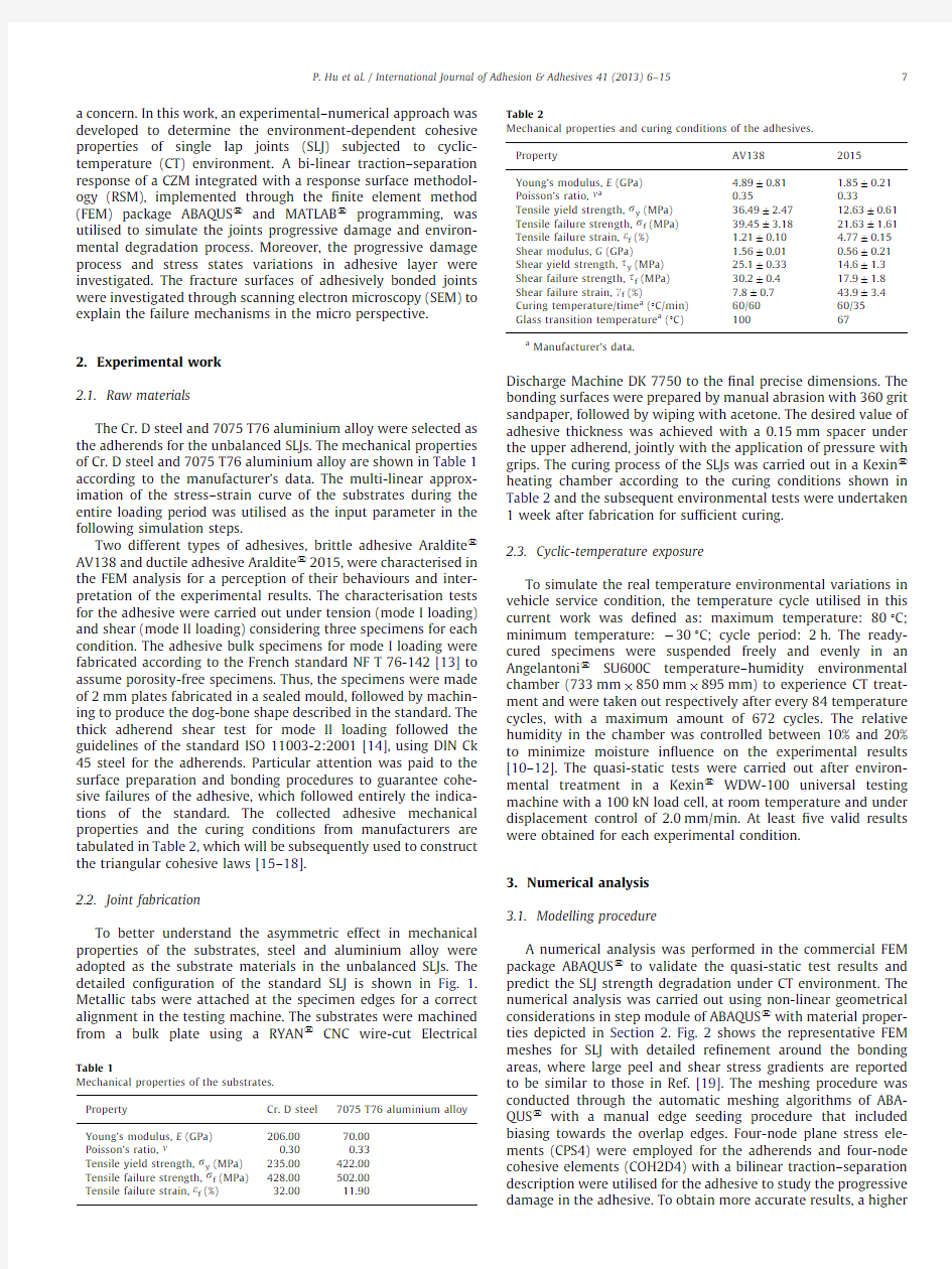
The Cr.D steel and7075T76aluminium alloy were selected as the adherends for the unbalanced SLJs.The mechanical properties of Cr.D steel and7075T76aluminium alloy are shown in Table1 according to the manufacturer’s data.The multi-linear approx-imation of the stress–strain curve of the substrates during the entire loading period was utilised as the input parameter in the following simulation steps.
Two different types of adhesives,brittle adhesive Araldite s AV138and ductile adhesive Araldite s2015,were characterised in the FEM analysis for a perception of their behaviours and inter-pretation of the experimental results.The characterisation tests for the adhesive were carried out under tension(mode I loading) and shear(mode II loading)considering three specimens for each condition.The adhesive bulk specimens for mode I loading were fabricated according to the French standard NF T76-142[13]to assume porosity-free specimens.Thus,the specimens were made of2mm plates fabricated in a sealed mould,followed by machin-ing to produce the dog-bone shape described in the standard.The thick adherend shear test for mode II loading followed the guidelines of the standard ISO11003-2:2001[14],using DIN Ck 45steel for the adherends.Particular attention was paid to the surface preparation and bonding procedures to guarantee cohe-sive failures of the adhesive,which followed entirely the indica-tions of the standard.The collected adhesive mechanical properties and the curing conditions from manufacturers are tabulated in Table2,which will be subsequently used to construct the triangular cohesive laws[15–18].
2.2.Joint fabrication
To better understand the asymmetric effect in mechanical properties of the substrates,steel and aluminium alloy were adopted as the substrate materials in the unbalanced SLJs.The detailed con?guration of the standard SLJ is shown in Fig.1. Metallic tabs were attached at the specimen edges for a correct alignment in the testing machine.The substrates were machined from a bulk plate using a RYAN s CNC wire-cut Electrical Discharge Machine DK7750to the?nal precise dimensions.The bonding surfaces were prepared by manual abrasion with360grit sandpaper,followed by wiping with acetone.The desired value of adhesive thickness was achieved with a0.15mm spacer under the upper adherend,jointly with the application of pressure with grips.The curing process of the SLJs was carried out in a Kexin s heating chamber according to the curing conditions shown in Table2and the subsequent environmental tests were undertaken 1week after fabrication for suf?cient curing.
2.3.Cyclic-temperature exposure
To simulate the real temperature environmental variations in vehicle service condition,the temperature cycle utilised in this current work was de?ned as:maximum temperature:801C; minimum temperature:à301C;cycle period:2h.The ready-cured specimens were suspended freely and evenly in an Angelantoni s SU600C temperature–humidity environmental chamber(733mm?850mm?895mm)to experience CT treat-ment and were taken out respectively after every84temperature cycles,with a maximum amount of672cycles.The relative humidity in the chamber was controlled between10%and20% to minimize moisture in?uence on the experimental results [10–12].The quasi-static tests were carried out after environ-mental treatment in a Kexin s WDW-100universal testing machine with a100kN load cell,at room temperature and under displacement control of2.0mm/min.At least?ve valid results were obtained for each experimental condition.
3.Numerical analysis
3.1.Modelling procedure
A numerical analysis was performed in the commercial FEM package ABAQUS s to validate the quasi-static test results and predict the SLJ strength degradation under CT environment.The numerical analysis was carried out using non-linear geometrical considerations in step module of ABAQUS s with material proper-ties depicted in Section2.Fig.2shows the representative FEM meshes for SLJ with detailed re?nement around the bonding areas,where large peel and shear stress gradients are reported to be similar to those in Ref.[19].The meshing procedure was conducted through the automatic meshing algorithms of ABA-QUS s with a manual edge seeding procedure that included biasing towards the overlap edges.Four-node plane stress ele-ments(CPS4)were employed for the adherends and four-node cohesive elements(COH2D4)with a bilinear traction–separation description were utilised for the adhesive to study the progressive damage in the adhesive.To obtain more accurate results,a higher
Table1
Mechanical properties of the substrates.
Property Cr.D steel7075T76aluminium alloy
Young’s modulus,E(GPa)206.0070.00
Poisson’s ratio,n0.300.33
Tensile yield strength,s y(MPa)235.00422.00
Tensile failure strength,s f(MPa)428.00502.00
Tensile failure strain,e f(%)32.0011.90Table2
Mechanical properties and curing conditions of the adhesives.
Property AV1382015
Young’s modulus,E(GPa) 4.8970.81 1.8570.21 Poisson’s ratio,n a0.350.33 Tensile yield strength,s y(MPa)36.4972.4712.6370.61 Tensile failure strength,s f(MPa)39.4573.1821.6371.61 Tensile failure strain,e f(%) 1.2170.10 4.7770.15 Shear modulus,G(GPa) 1.5670.010.5670.21 Shear yield strength,t y(MPa)25.170.3314.671.3 Shear failure strength,t f(MPa)30.270.417.971.8 Shear failure strain,g f(%)7.870.743.973.4 Curing temperature/time a(1C/min)60/6060/35
Glass transition temperature a(1C)10067
a Manufacturer’s data.
P.Hu et al./International Journal of Adhesion&Adhesives41(2013)6–157
mesh density with the mesh size of 0.15mm ?0.15mm was adopted for the cohesive elements throughout the adhesive bond line,which was obtained through a mesh convergence study with 0.1mm,0.15mm and 0.3mm sizes taken into consideration [20,24].Moreover,one end of the adherend was constrained by an encastre constraint,while the translation in the transverse direction and rotation about the out of plane direction of the other end were restrained.Finally the simulation process was implemented within ABAQUS s CAE suite and the results will be discussed in the following sections.Besides,it is worth noting that a small level of viscous damping factor (10à5)was utilised in the constitutive equation of the cohesive elements to avoid possible numerical instability when the simulation procedure is close to catastrophic failure [20].3.2.Cohesive zone model
The cohesive zone model,as shown in Fig.3,combines an initial elastic branch,a strength based damage initiation criterion and a fracture mechanics based damage propagation softening branch.This model was introduced by Barenblatt [21,22]and incorporated into a computational framework by Hillerborg et al.[23].Incorporating a small process zone ahead of the crack tip where material yielding,micro-cracking,and void formation is observed,the CZM is frequently used in numerical analysis.In this work,the most commonly adopted bilinear traction–separation response of a CZM was adopted to model the bond line for both mode I and mode II responses.
The de?ning parameters of a mixed-mode traction–separation response include the fracture energies for mode I and mode II (G IC ,G IIC ),the tripping tractions for mode I and mode II (T I ,T II ),the initial stiffnesses for mode I and mode II (E I ,E II )and the mode mix criteria,where subscripts I and II represent the normal and shear components,respectively.The areas under the traction–separation laws in each mode of loading equal to the respective fracture energy (G C ).The stress state of each mode where the adhesive damage process initiates relates to the tripping traction (T ),while the initial stiffness (E )corresponds to the adhesive
Young’s and shear modulus.Moreover,the mode mix criteria of a CZM quantify the relative proportions of normal and shear deformation and the energetic criterion is adopted in this work to simulate the typical mixed-mode behaviour [24].
The traction–separation law assumes an initial linear elastic behaviour followed by a linear damage evolution.Damage initia-tion can be speci?ed through different criteria.In this work,the maximum nominal stress criterion was introduced signifying that damage is assumed to initiate when either of the peel or shear traction (t I or t II )exceeds the tripping traction (T I or T II )as expressed in the following equation:
max /t I S I ,t II
II ?1e1T
where /S is the Macaulay bracket meaning that compression stress state does not lead to damage initiation.After the peak traction value in Fig.3,a linear softening stage https://www.sodocs.net/doc/bc3333213.html,plete separation of the adhesive layer is determined by a quadratic power-law form criterion as de?ned in the following equation:G I G IC 2tG II G IIC 2
?1e2Tin which G I and G II are the energies released by the traction due to the respective separation in normal and shear directions,respec-tively.Table 3shows the calibrated CZM parameters introduced in ABAQUS s for the simulation of damage growth in the adhesive layer.The values of fracture energies were typically of the range of values found in the literatures for the AV138and 2015adhesives [25–27].These were re?ned along with the tripping tractions in an iterative technique to match the static failure loads.These properties were obtained by correlation between the simulated and experimental (quasi-static test)failure loads on the SLJs [20,24].It is worth noting that the selected cohesive para-meter sets for both studied adhesives may not be unique.Different sets of the cohesive parameters may result in the variation in the load-versus-displacement curve as presented in Fig.4discussed
below.
Fig.1.Con?guration of the single lap
joint.
Fig.2.Finite element mesh for single lap joint with detailed re?nement around the bonding areas.
P.Hu et al./International Journal of Adhesion &Adhesives 41(2013)6–15
8
The simulated and predicted SLJ load-versus-displacement curves are summarised in Fig.4.The experimental curves are obtained from the output of the universal testing machine,while the predicted curve is calculated from the reaction force data of the nodes at the ?xed end of the substrate.As can be seen,the experimental and simulated joint peak loads match well with each other,with relative errors of 0.188%and 0.208%for AV138and 2015,respectively.Besides,the predicted joint displacement at the point of peak load is also close to the experimental average failure displacement,with relative errors of 9.597%and 9.319%for AV138and 2015,respectively.It is worth noting that the experi-mental loading process was a quasi-static treatment,which introduced certain additional (dynamic)stiffness into the joint system and led to the fact that the slope in experimental curve is larger than the numerical one in the initial stage.The in?uence of additional stiffness was included into the numerical model to provide a better ?tting between the experimental and numerical curves in the overall variation
trend.
Fig.3.Schematic damage process zone and bilinear traction–separation cohesive zone model.
Table 3
Calibrated traction–separation response for AV138and 2015.Parameter
AV138
2015
Initial stiffness —mode I/mode II (MPa)4890/15601850/560Tripping traction —mode I/mode II (MPa)27.50/15.8022.50/16.30Fracture energy —mode I/mode II (kJ/m 2)0.30/2.100.35/2.80Initiation criterion Maximum nominal stress criterion Propagation criterion
Quadratic power
law
Fig.4.Experimental and predicted load-versus-displacement curves for SLJs bonded with AV138(a)and 2015(b).
P.Hu et al./International Journal of Adhesion &Adhesives 41(2013)6–159
4.Results and discussion
In all joints tested,fracture of the specimens occurred at the adhesive layer exhibiting a cohesive failure,which proved the effectiveness of the surface preparation mentioned in Section 2.4.1.CZM modelling results
In the simulation procedures,through modelling the adhesive layer as a traction–separation CZM law,fracture occurred due to cohesive crack propagation in the adhesive bond line,initiating at the overlap edge closer to the aluminium alloy substrate side with fast propagation to the inner regions of the bond.Fig.5shows the representative failure process in the bond line of the SLJ bonded with 2015adhesive from damage initiation to complete failure,while the SLJ experimentally-measured and simulated deforma-tions at the complete failure status are also compared.The parameter SDEG,de?ned as the overall value of the scalar damage variable in ABAQUS s terminology,corresponds to the stiffness degradation of the adhesive layer,with SDEG ?0relating to undamaged material and SDEG ?1to complete failure [17,28].As can be seen in Fig.5(a)–(c),the adhesive layer using CZM modelling experiences the full process of damage propagation,including the damage initiation phase (a),crack propagation phase (b)and the complete failure status (c).By comparing the simulated and experimentally-measured deformations of the SLJs at complete failure status,as shown in Fig.5(c)and (d),plastic transverse de?ection was observed only at the free end of steel substrate,resulting in the existence of residual stress near the overlap edge.The transverse de?ection caused by plastic defor-mation at the free end of steel substrate was also measured in both simulated and tested substrates.Through comparing the
simulated 1.85mm displacement and the digital-calliper mea-sured 1.96mm one (with a relative error of 5.6%),the CZM modelling utilised in this work proved to be consistent to the real deformation occurred in SLJs and feasible to predict the damage propagation and stress state in SLJs.
4.2.Strength prediction
According to the experimental work described in Section 2and the corresponding experimental results discussed in the following,the joint strengths of the tested specimens bonded with both adopted adhesives showed a relative rapid degradation in the initial cycles and levelled off after certain exposure period.From the point of view of different curing conditions and glass transition temperatures of the adhesives shown in Table 2,there are three major processes in adhesive layer as the specimens are kept in the environmental chamber [29–31]:the post curing process,the temperature degradation process and the adhesive drying process.In the previous study,adhesive joint bonded with 2015adhesive was exposed in the environment chamber at 801C for 7?24h and the quasi-static test revealed that joint strength increased by 11.698%after the exposure treatment.The post-curing process and the low glass transition temperature of 2015adhesive are considered to be the main reasons leading to this phenomenon.As a result of the post curing process,the internal stress in adhesive layer induced in curing heating stage is released in a certain amount as the adhesive turns more ?exible with the rise in temperature (especially after the temperature exceeds the adhesive glass transition temperature),which can in some extent offset the temperature degradation caused by the long-term cyclic thermal loading.Meanwhile,it is assumed that the adhe-sive drying process strengthens the bonding effect equally
in
Fig.5.Failure process in the adhesive layer of SLJ bonded with 2015adhesive using CZM:damage initiation at the overlap edge closer to the aluminium substrate side (a);crack propagation to inner regions (b);simulated (c)and experimental (d)complete failure statuses.
P.Hu et al./International Journal of Adhesion &Adhesives 41(2013)6–15
10
adhesive joints with the same length of experimental period,as the relative humidity in the chamber is kept at the same level.
Considering the above mentioned three environmental pro-cesses as a whole,it is reasonable to introduce an environmental degradation factor Deg to represent the cyclic-temperature in?u-ence on adhesively-bonded-joint strength.The environmental degradation factor Deg varies from 1to 0,demonstrating the degradation process in the adhesive layer.In the CZM modelling adopted in this work,the key parameters that affect the adhesive behaviour include the adhesive Young’s and shear moduli,the tripping tractions for mode I and mode II and the fracture energies for mode I and mode II.It was assumed for simplicity that all the three material properties will be degraded equally through being multiplied by Deg,based on previous experimental work by Liljedahl [32].The representative degradation process for a triangular traction–separation response CZM is illustrated in Fig.6.It is shown that a certain value of environmental degrada-tion factor Deg causes signi?cant changes in the traction–separation response pro?les:the slope of the initial elastic branch and the peak value of traction decreases and the overall area under the triangular curve becomes smaller.
Through implementing similar CZM-parameter calibrating procedure as described in Section 3for different CT cycle amounts,the experimental and predicted SLJ peak loads for AV138and 2015adhesives are presented in Fig.7,with a third-order polynomial ?tting of numerical tendency to show the joint strength variation trend.Observing the variations of the triangles with error bars in Fig.7,it is found that the experimentally-measured joint strengths for both adhesives show a decreasing trend with smaller gradient as the temperature cycle increases.Besides,it is also found through the error bars that the standard deviations in experimental peak load generally get larger after
temperature exposure treatments,signifying that the adhesive joint strength tends to be unstable due to the cyclic thermal loading.Meanwhile,it is observed that,for both AV138and 2015bonded SLJs,the utilised CZM modelling technique provided accurate approximation with the experimental results.
Furthermore,since the environmental degradation process in the introduced CZM modelling was essentially controlled by the environmental degradation factor Deg,it was sensible to investi-gate the variation of Deg to understand the intrinsic in?uence of CT thermal loading on adhesively bonded joints.The variation processes of Deg for both AV138and 2015bonded SLJs as a function of CT cycle amount are tabulated in Table 4.It was concluded that the key parameters in CZM modelling experienced 2.7%and 5.5%degradation for AV138and 2015bonded SLJs,respectively,signifying that the ductile adhesive 2015tends to be more likely to be affected by cyclic-temperature environment than brittle adhesive AV138.
4.3.Adhesive stress state
To essentially understand the effects of CT environmental treatment on the SLJ mechanical behaviour,the internal stress state variations in adhesive layer after CT treatments were investigated through the above validated CZM modelling techni-que.In this section,the adhesive layer stress state before damage initiation for different environmental conditions was studied.The stress state at a grips displacement of 0.05mm was utilised,because no damage initiation was observed in all the tested SLJs at the 0.05mm displacement.Moreover,both peel and shear stresses plotted are normalised by t avg ,the average value of t xy along the overlap direction for each CT condition.The normalised peel and shear stress states for AV138and 2015under 0and 672CT cycles are shown in Fig.8.
In general,as presented in Fig.8,the stress pro?les are generally consistent with the typical distributions documented in the literatures [33–35].The peel stresses (Fig.8(a)and (b))show singularities caused by the shape geometry change at the overlap edges and a large gradient at the nearby regions [36].The peel stresses reported are compressive at the inner overlap regions,although much smaller in magnitude than t avg .The shape of the peel stress is caused by the joint eccentricity,leading to the adherends deformation that results in opening at the overlap edges and compression in-between [37].The shear stresses (Fig.8(c)and (d))show the typical concave shape pro?les,with smaller magnitudes at the inner region and peaking at the overlap edges [38].This shape is accredited to the differential deformation between the substrates along the bond line [5,39
].
Fig.6.Degradation process for a triangular traction–separation response
CZM.
Fig.7.Experimental and predicted SLJ peak loads as a function of CT cycle amount for AV138(a)and 2015(b).
P.Hu et al./International Journal of Adhesion &Adhesives 41(2013)6–1511
More speci?cally,through comparing the variations in stress shapes between AV138and 2015,it is investigated that both the normalised peel and shear stresses in 2015bonded SLJ (Fig.8(b)and (d))are much smaller in magnitude at the peak value and the stress gradient than the AV138ones (Fig.8(a)and (c)),signifying that ductile adhesive (2015)bears less stress concentration in bonding line than brittle adhesive (AV138)[1,5,8].Moreover,through comparing the stress pro?les in the
bonding areas near the steel and the aluminium alloy substrate
side (corresponding to the adhesive layer with a negative or a positive x coordinate),it is found that,for both peel and shear stresses,the stress concentration tends to be more severe in the bonding areas near the aluminium alloy substrate (less stiff in modulus than steel substrate).This is justi?ed through the existence of not only the larger stress gradients in the adhesive layer with positive x coordinates,but also the bigger stress peak values at the overlap edges near the aluminium alloy adherend [8,40–42].In conclusion,stiff adherend and ductile adhesive bene?t to a better stress distribution,resulting in the enhance-ment in joint strength.
Furthermore,the stress states in adhesive layer under 0and 672CT cycles are investigated through enlarged views of the signi?cant stress concentration regions marked in Fig.8.Similar tendencies are observed for both peel and shear stress states under 0and 672CT cycles through the comparison of the marked zones in Fig.8,signifying that for a certain type of adhesive,the
Table 4
Variation processes of Deg as a function of CT cycle amount for AV138and 2015bonded SLJs.Cycle amount
084
168
252
336
420
504
588
672
Deg for AV13810.9950.9900.9820.9800.9790.9770.9740.973Deg for 201510.9790.9610.9530.9510.9490.9480.947
0.945
Fig.8.Stress state in undamaged adhesive layer under 0and 672CT cycles:normalised peel stress for AV138(a)and 2015(b);normalised shear stress for AV138(c)and 2015(d).
P.Hu et al./International Journal of Adhesion &Adhesives 41(2013)6–15
12
stress concentration severity slightly increases after a 672-period extreme CT exposure,since the normalised peak stress values at the overlap edges and the stress gradients near the overlap edges both experience an increase as shown in the ampli?ed marked zones.
4.4.RSM analysis
Based on the experimental and predicted results of environ-mental degradation factor Deg as concluded in Table 4,RSM analysis was performed to understand the effects of CT exposure period and adhesive stiffness on the corresponding Deg response [43,44].Taking C as the CT cycle amount and S as the adhesive shear modulus,the environmental degradation factor Deg is obtained through a MATLAB s -programme-realized RSM given as
Deg ?9:330t5:268e à3C t3:480S t5:067e à6C 2
à1:725e à2CS à4:357S 2à5:153e à9C 3
t4:398e à6C 2S t1:311e à3CS 2à6:890e à2S 3à1:580e à12C 4t4:346e à9C 3S à4:837e à6C 2S 2
t4:657e à3CS 3t1:032S 4
=10
e3T
To verify the feasibility and accuracy of the obtained Deg response,the relative errors between RSM results and predicted results at the sample points are shown in Fig.9(a).Based on the relative error comparison,it is found that a maximum relative error of 0.209%is obtained,proving that the Deg response satis?es well with the predicted results and can approximately show the real relationship between factors and response.According to the expression of Deg response given in Eq.(3),the corresponding response surface contour is presented in Fig.9(b).
Investigating the contour variation of Deg response along the CT cycle amount axis in Fig.9(b),it is observed that an obvious degradation process occurs as the exposure period gets longer,while the degradation gradient tends to get smaller with the increase in cycle amount,which indicates that the adhesively bonded joint strength is degraded by the extreme CT treatment and a plateau of joint strength is likely to achieve after certain CT cycles.Meanwhile,it can be also judged from the Deg variation along the adhesive shear modulus axis that,the degradation effects lessen as the adhesive stiffness goes up,signifying that
stiff adhesives tend to be less sensitive in joint performance to the environmental in?uence than ?exible adhesives.
4.5.Fracture surface SEM investigation
Scanning electron microscopy (SEM)was utilized in this section to investigate the fracture surfaces of joints bonded with dissimilar adhesives before and after CT exposure treatments [45,46].The fracture surfaces from SEM of representative adhe-sively bonded joints bonded with AV138and 2015before and after 672CT cycles are presented in Fig.10,obtained from a FEI s Quanta 200microscope.As shown in Fig.10,the fracture surfaces consist of a few bright patches that are scattered unevenly on an otherwise dark background.A close examination of a typical patch reveals that the bright surface is near the substrate whereas the dark surface is covered by adhesive.
For the fracture surfaces of adhesive joints bonded with AV138before and after 672CT cycles,through comparing the marked zones in Fig.10(a)and (b),it is found that the micro distribution characteristics in failure surface experience a signi?cant transi-tion,varying from large-whole pieces of residual adhesive scat-tered on the substrate before CT exposure to small-blocky pieces of adhesive after.Similar and even more signi?cant tendency was found in the 2015bonded joints,as shown in the marked zones from Figs.10(c)and 9(d).In Fig.10(c),i.e.2015bonded joints before CT exposure,hardly relative large-bulk pieces of residual adhesive can be observed in the corresponding fracture surfaces.However,for 2015bonded joints after CT treatment as presented in Fig.10(d),the majority of the micro-scale failure surface is comprised of small fragments of adhesive.The similar distribu-tion tendency variations,found in both the adhesives bonded SLJs,signi?es the transition in adhesive toughness from ductility to brittleness.Moreover,from the investigated variation extents between the two studied adhesives,it can be judged that ductile adhesive 2015exhibits a stronger sensitivity to environmental change,causing more signi?cant transition in micro fracture surface distribution as shown in Fig.10(c)and (d).This transition phenomenon is consistent with the fact,that the environmental degradation factor Deg for 2015adhesive experienced a larger degradation process (5.5%)than the Deg for AV138(2.7%),as discussed earlier in Section 4.2and Table 4,providing an explana-tion from the micro-scale
perspective.
Fig.9.Relative error of Deg between RSM and predicted results (a)and the Deg response surface contour (b).
P.Hu et al./International Journal of Adhesion &Adhesives 41(2013)6–1513
5.Conclusions
A combined experimental–numerical approach was developed to characterise the effect of cyclic-temperature environment on adhesively bonded joints.The environmental degradation factor Deg was introduced into an ABAQUS s -realised cohesive zone model to evaluate the degradation process in the adhesive layer caused by the cyclic-temperature environment and the stress states in adhesive layer before and after CT environment were investigated.Carefully designed experimental tests were carried out to validate the simulation results and help the numerical procedure to predict joint mechanical behaviour after environ-mental exposure.A RSM process was undertaken to help better understand the relationship between the selected factors and the Deg response.The following conclusions were drawn:
(a)Using the cohesive-zone ?nite element model of the single lap
joint,the cohesive properties of the adhesive layer can be properly calibrated against the experimental data.
(b)The introduced environmental degradation factor Deg can
effectively characterise and predict the degradation process in the cohesive properties brought about by the cyclic-temperature environment,with a 2.7%and a 5.5%degradation for AV138and 2015,respectively.
(c)The stress states in adhesive layer experienced a similar slight
?uctuation after CT treatment in both adhesives studied,signifying that the stress concentration becomes more severe due to the combined environmental in?uence brought about
by the post curing process,the temperature degradation process and the adhesive drying process.
(d)Through the outlined Deg response surface using a RSM
analysis,the ?uctuation tendency of Deg varying with tem-perature cycle amount and adhesive modulus was better observed through a 3D contour map.
(e)Scanning electron microscopy was utilised to understand the
micro fracture mechanisms of adhesively bonded joints bet-ter.Detailed observation revealed that small-blocky pieces of residual adhesive came into being on the failure surfaces of joints after CT exposure,demonstrating the transition to brittleness in adhesive toughness.Acknowledgements
The authors gratefully acknowledge ?nancial support from the Key Project of the National Natural Science Foundation of China (no.10932003),‘‘973’’National Basic Research Project of China (nos.2010CB736104and 2010CB832700),and ‘‘04’’Great Project of Ministry of Industrialization and Information of China (no.2011ZX04001-021).Many thanks are due to Professor Andrew Crocombe for the valuable instructions.References
[1]da Silva LFM,Ochsner A,Adams RD.Handbook of adhesion technology.
Heidelberg:Springer;
2011.
Fig.10.Fracture surfaces from SEM of representative adhesively bonded joints bonded with:AV138before (a)and after (b)CT treatments;2015before (c)and after (d)CT treatments.
P.Hu et al./International Journal of Adhesion &Adhesives 41(2013)6–15
14
[2]Higgins A.Adhesive bonding of aircraft structures.Int J Adhes Adhes
2000;20:367–76.
[3]Dilger K.Automobiles.In:Adams RD,editor.Adhesive bonding:science,
technology and applications.Cambridge:Woodhead publishing Ltd;2005.
p.357–85.
[4]Hart-Smith LJ.Aerospace.In:Adams RD,editor.Adhesive bonding:science,
technology and applications.Cambridge:Woodhead publishing Ltd;2005.
p.489–527.
[5]Adams RD,Comyn J,Wake WC.Structural adhesives joints in engineering.
2nd ed.London:Chapman&Hall;1997.
[6]Hu P,Han X,Li L,Shao Q,Li WD.Effect of temperature on shear strength of
adhesively bonded joints for automobile industry.Adv Mater Res 2012;418:1259–65.
[7]Messler RW.Joining of advanced material.Boston:Butterworth-Heinemann;
1993.
[8]Kinloch AJ.Adhesion and adhesives:science and technology.London:Chap-
man and Hall;1983.
[9]Banea MD,da Silva LFM,Campilho RDSG.Mode I fracture toughness of
adhesively bonded joints as a function of temperature:experimental and numerical study.Int J Adhes Adhes2011;31:273–9.
[10]Liljedahl CDM,Crocombe AD,Wahab MA,Ashcroft IA.Modelling the
environmental degradation of adhesively bonded aluminium and composite joints using a CZM approach.Int J Adhes Adhes2007;27:505–18.
[11]Katnam KB,Sargent JP,Crocombe AD,Khoramishad H,Ashcroft IA.Char-
acterisation of moisture-dependent cohesive zone properties for adhesively bonded joints.Eng Fract Mech2010;77:3105–19.
[12]Bordes M,Davies P,Cognard JY,Sohier L,Sauvant-Moynot V,Galy J.
Prediction of long term strength of adhesively bonded steel/epoxy joints in sea water.Int J Adhes Adhes2009;29:595–608.
[13]NF T76-142.Me′thode de preparation de plaques d’adhe′sifs structuraux pour
la re′alisation d’e′prouvettes d’essai de caracte′risation,1988.
[14]ISO11003-2:2001.Adhesives—determination of shear behaviour of struc-
tural bonds,part II:thick adherend tensile test method,1993.
[15]Pinto AMG,Campilho RDSG,Mendes IR,Aires SM,Baptista APM.Effect of hole
drilling at the overlap on the strength of single-lap joints.Int J Adhes Adhes 2011;31:380–7.
[16]da Silva LFM,Adams RD.Joint strength predictions for adhesive joints to be
used over a wide temperature range.Int J Adhes Adhes2007;27:362–79. [17]Campilho RDSG,Banea MD,Pinto AMG,da Silva LFM,de Jesus AMP.Strength
prediction of single-and double-lap joints by standard and extended?nite element modelling.Int J Adhes Adhes2011;31:363–72.
[18]da Silva LFM,da Silva RAM,Chousal JAG,Pinto AMG.Alternative methods to
measure the adhesive shear displacement in the thick adherend shear test.J Adhes Sci Technol2008;22:15–29.
[19]Panigrahi SK,Pradhan B.Three dimensional failure analysis and damage
propagation behaviour of adhesively bonded single lap joints in laminated FRP composites.J Reinf Plast Compos2007;26:183–201.
[20]Khoramishad H,Crocombe AD,Katnam KB,Ashcroft IA.Predicting fatigue
damage in adhesively bonded joints using a cohesive zone model.Int J Fatigue2010;32:1146–58.
[21]Barenblatt GI.Equilibrium cracks formed on a brittle fracture.Dokl Akad
Nauk SSSR1959;127:47–50.
[22]Barenblatt GI.The mathematical theory of equilibrium cracks in brittle
fracture.Adv Appl Mech1962;7:55–129.
[23]Hillerborg A,Modeer M,Petersson PE.Analysis of crack formation and crack
growth in concrete by means of fracture mechanics and?nite elements.Cem Concr Res1976;6:773–81.[24]Khoramishad H,Crocombe AD,Katnam KB,Ashcroft IA.Fatigue damage
modelling of adhesively bonded joints under variable amplitude loading using a cohesive zone model.Eng Fract Mech2011;78:3212–25.
[25]Campilho RDSG,Pinto AMG,Banea MD,Silva RF,da Silva LFM.Strength
improvement of adhesively-bonded joints using a reverse-bent geometry.
J Adhes Sci Technol2011;25:2351–68.
[26]de Moura MFSF,Campilho RDSG,Goncalves JPM.Crack equivalent concept
applied to the fracture characterisation of bonded joints under pure mode I https://www.sodocs.net/doc/bc3333213.html,pos Sci Technol2008;68:2224–30.
[27]da Silva LFM,de Magalh~a es FACRG,Chaves FJP,de Moura MFSF.Mode II
fracture toughness of a brittle and a ductile adhesive as a function of the adhesive thickness.J Adhes2010;86:889–903.
[28]ABAQUS s HTML Documentation.Dassault Systemes,2009.
[29]Pearce PJ,Ennis BC,Grabovac I,Morris CEM.Off-optimum cure of aerospace
epoxy adhesives.J Adhes1994;47:123–32.
[30]Sancaktar E.Fracture aspects of adhesive joints:material,fatigue,interphase,
and stress concentration considerations.J Adhes Sci Technol1995;9:119–47.
[31]Zhou DP.The viscoelasticity and stress relaxation of the adhesive layer.Chin
J Adhes1997;18:1–5.
[32]Liljedahl CDM.Modelling the interfacial degradation in adhesively bonded
joints.PhD Thesis.Guildford,Surrey,UK:University of Surrey;2006. [33]Campilho RDSG,de Moura MFSF,Barreto AMJP,Morais JJL,Domingues JJMS.
Experimental and numerical evaluation of composite repairs on wood beams damaged by cross-graining.Constr Build Mater2010;24:531–7.
[34]Shin KC,Lee JJ.Bond parameters to improve tensile load bearing capacities of
co-cured single and double lap joints with steel and carbon?ber–epoxy composite adherends.J Compos Mater2003;37:401–20.
[35]Yang YK,Liao ZK,Yu YZ,Lu FC.Synthetic adhesive.Beijing:Science Press;
1980.
[36]Radice J,Vinson J.On the use of quasi-dynamic modeling for composite
material structures:analysis of adhesively bonded joints with midplane asymmetry and transverse shear https://www.sodocs.net/doc/bc3333213.html,pos Sci Technol 2006;66:2528–47.
[37]Pinto AMG,Magalh~a es AG,Campilho RDSG,de Moura MFSF,Baptista APM.
Single-lap joints of similar and dissimilar adherends bonded with an acrylic adhesive.J Adhes2009;85:351–76.
[38]Luo Q,Tong L.Fully-coupled nonlinear analysis of single lap adhesive joints.
Int J Solids Struct2007;44:2349–70.
[39]Volkersen O.Die Nietkraftverteilung in zugbeanspruchten Nietverbindungen
mit konstanten Laschenquerschnitten.Luftfahrtforschung1938;15:41–7. [40]McGeorge D.Inelastic fracture of adhesively bonded overlap joints.Eng Fract
Mech2010;77:1–21.
[41]John SJ,Kinloch AJ,Matthews FL.Measuring and predicting the durability of
bonded carbon?bre/epoxy composite https://www.sodocs.net/doc/bc3333213.html,posites1991;22:121–7. [42]Ahn SH,Springer GS.Repair of composite laminates-I:test results.J Compos
Mater1998;32:1036–74.
[43]Avalle M,Chiandussi G,Belingardi G.Design optimization by response
surface methodology:application to crashworthiness design of vehicle structures.Struct Multidiscip Optim2002;24:325–32.
[44]Lee SH,Kim HY,Oh SI.Cylindrical tube optimization using response surface
method based on stochastic process.J Mater Process Technol2002;130–131:490–6.
[45]Reis PNB,Ferreira JAM,Antunes F.Effect of adherend’s rigidity on the shear
strength of single lap adhesive joints.Int J Adhes Adhes2011;31:193–201.
[46]Lu ZG,Wang PC,Lin JP,Wang LY,Li G.Effect of moisture content in uncured
adhesive on static strength of bonded galvanized DP600steel joints.Int J Adhes Adhes2011;31:202–8.
P.Hu et al./International Journal of Adhesion&Adhesives41(2013)6–1515