The investigation on the machining process of BTA deep hole drilling
The investigation on the machining process of
BTA deep hole drilling
C.H.Gao a ,K.Cheng a,*,
D.Kirkwood b
a
School of Engineering,Leeds Metropolitan University,Calverley Street,Leeds LS13HE,UK
b
Department of Engineering,Glasgow Caledonian University,Cowcaddens Road,Glasgow G40BA,UK
Abstract
In this paper,a computer-based approach is presented to the investigation of machining mechanisms in boring and trepanning association (BTA)deep hole drilling processes.The cutting mechanisms investigated are focused on the chip deformation and associated drilling forces in deep hole situation in particular.The machining models are further investigated for such processes.The models are evaluated and validated based on the data acquired with a computer-based acquisition system.It is found that the chip deformation cut by the centre edge is the largest,whereas the change tendency of the cutting force and the sum of chip deformation cut by three blades of drill are about the same.This paper also describes the measurement and analysis of the forces including the axial force in BTA deep hole machining.#2000Elsevier Science B.V .All rights reserved.
Keywords:BTA deep hole drilling;Chip deformation;Cutting force;Wear
1.Introduction
In machining processes such as turning,milling and shaping,a large chip discharge space is normally available and the chip breaker is often big enough to ensure the chip discharging.But in the process of drilling,deep hole drilling in particular,no suf?cient discharging space is available,and so peck drilling,axial vibration and pressurised cutting ˉuid are often used to help chip discharging.A satisfactory chip discharge is essential for implementing successful deep hole drilling.
The interaction between the drilling tool and the work-piece in BTA deep hole machining has been studied to determine the inˉuence of various machining conditions on the chip deformation,cutting forces and the tool wear [1±3].Since the resultant drilling force in axial direction consists of the cutting force,ˉuid pressure force,burnishing force and friction,using a complete theoretical approach based on derived equations to precisely estimate the resul-tant force would be dif?cult and impractical [4].
In this paper an experiment based approach is proposed to investigate the BTA deep hole drilling process.The inves-tigation is focused on the chip deformation,tool wear and the associated drilling forces.A computer-based data acqui-sition system and an optical ?bre force sensor is used for sampling the machining data.This study is essential for further developing an on-line monitoring system for con-trolling the machining process.
2.Experimental procedure and equipment
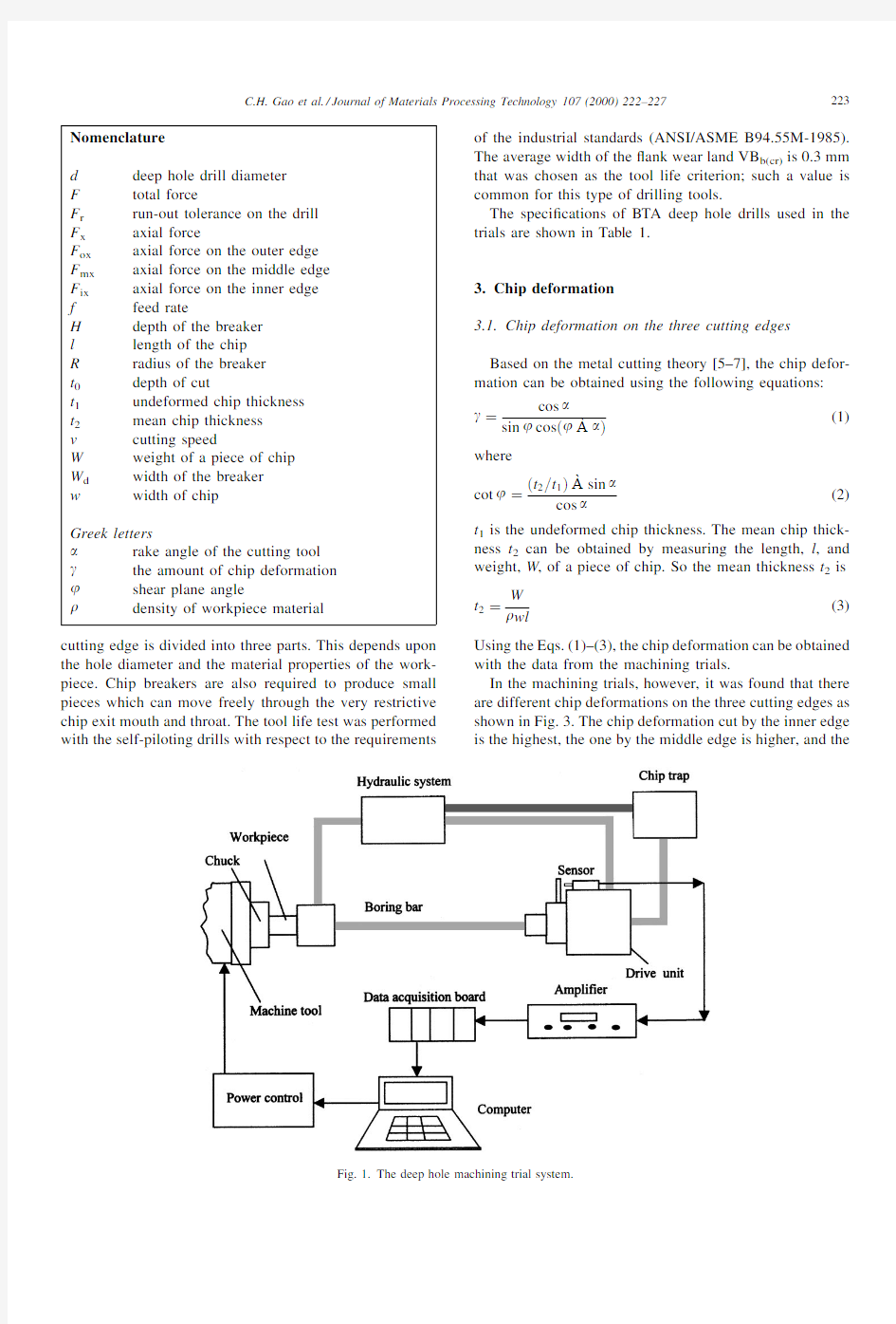
The experimental system is mainly composed of the deep hole drilling machine tool and the data acquisition/analysis system as shown in Fig.1.The system details are as follows:1.Cooling system:
cutting fluid flow rate,q 100l a min; cutting fluid pressure,p 2X 50MPa; cooling liquid,emulsions.
2.Sensor:optical ?bre force sensor.
3.Small signal ampli?er: accuracy,1%;
response frequency,2kHz; output draft amount,<2mV .4.Drill material:carbide blade.
5.Workpiece material:AISI1045,200HB.
Fig.2shows the con?guration of a typical BTA drilling tool head.The head nose is designed offset from the axis of the head.308negative rake angle is chips in C shape which must be small enough to go out introduced to strengthen the cutting edge in that area.In order to obtain narrow chips,
the
Journal of Materials Processing Technology 107(2000)222±227
*
Corresponding author.Tel.: 44-113-2833098;fax: 44-113-2833110.
E-mail address :k.cheng@https://www.sodocs.net/doc/8b17748152.html, (K.Cheng).
0924-0136/00/$±see front matter #2000Elsevier Science B.V .All rights reserved.PII:S 0924-0136(00)00684-1
cutting edge is divided into three parts.This depends upon the hole diameter and the material properties of the work-piece.Chip breakers are also required to produce small pieces which can move freely through the very restrictive chip exit mouth and throat.The tool life test was performed with the self-piloting drills with respect to the requirements of the industrial standards(ANSI/ASME B94.55M-1985). The average width of theˉank wear land VB b(cr)is0.3mm that was chosen as the tool life criterion;such a value is common for this type of drilling tools.
The speci?cations of BTA deep hole drills used in the trials are shown in Table1.
3.Chip deformation
3.1.Chip deformation on the three cutting edges Based on the metal cutting theory[5±7],the chip defor-mation can be obtained using the following equations:
g
cos a
sin j cos jàa
(1) where
cot j
t2a t1 àsin a
cos a
(2) t1is the undeformed chip thickness.The mean chip thick-ness t2can be obtained by measuring the length,l,and weight,W,of a piece of chip.So the mean thickness t2is t2
W
r wl
(3)
Using the Eqs.(1)±(3),the chip deformation can be obtained with the data from the machining trials.
In the machining trials,however,it was found that there are different chip deformations on the three cutting edges as shown in Fig.3.The chip deformation cut by the inner edge is the highest,the one by the middle edge is higher,and
the
Fig.1.The deep hole machining trial system.
C.H.Gao et al./Journal of Materials Processing Technology107(2000)222±227223
one by the outer edge is the smallest.The reasons are as follows:
The rake angles on the three cutting edges are different.The right rake angle of the inner edge is à308,as shown in Fig.2.The rake angles of the other two cutting edges are in the range of 0$28.Due to the chip deformation principles [5],the chip deformation cut by the inner edge will be larger than those by other edges,which is con-sistent with the trial results as shown in Fig.4.
The tangential velocities on the three edges are different.Because there are different radii on the three cutting edges,the speed of outer edge is the highest,the one of middle edge is higher,and the one of the inner edge is the smallest.These determine the chip deformation cut by the inner edge being larger than those by others.
The breaker and chip mouth wall.When the chip is removed from the workpiece,the up-curling chip cut by the inner edge will strike the chip mouth except when it strikes the breaker and the workpiece.So
its
Fig.2.A typical BTA drill head used in the drilling trials.
Table 1
Speci?cations of the BTA deep hole drills used in the trials Drill No.D (mm)Cutting edge a Clearance angle F r (mm)W d (mm)H (mm)R (mm)125Outer edge 2836H 6821H 0.10 1.560.39 1.1Middle edge 287826H 0.1 1.650.51 1.1225Outer edge à6834H 881H 0.08 1.300.62 1.0Middle edge à3813H 8856H 0.08 1.440.63 1.0325Outer edge 286H 881H 0.05 1.370.32 1.0Middle edge 2837H 8858H 0.05 1.470.48 1.0425Outer edge 18H 7811H 0.04 1.350.38 1.1Middle edge 2826H 7818H 0.04 1.660.56 1.15
25
Outer edge 1830H 9817H 0.05 1.140.37 1.0Middle edge
185H
9832H
0.06
1.19
0.44
1.0
Fig.3.The chip deformation resulting from the three cutting
edges.
Fig.4.The variation of mean deformation.
224 C.H.Gao et al./Journal of Materials Processing Technology 107(2000)222±227
deformation will increase and be bigger than the other two.
3.2.Effects of the machining conditions
The chip deformation will be affected by the machining conditions.In the drilling trials,the effects of tool rake angle,speed and feed rate were investigated.It was found: When the cutting speed increases,the chip deformation will decrease (as shown in Fig.5).
When the feed rate increases,the chip deformation will increase (as shown in Fig.4).
When the rake increases,the chip deformation will decrease (as shown in Fig.4).These conclusions are very similar to those derived in turning [7].4.Cutting force
The cutting force on the drill consists of the cutting force on the three cutting edges,ˉuid pressure,burnishing force and friction of the pad [8].In the trials,only the axial force was measured.Considering the experimental conditions,the depth of cutting was the same.The axial force was measured by the optical sensor in the systems,as shown in Fig.1.It was found:
When the speed increases,the axial cutting force will decrease,which is shown in Fig.6.
When the feed rate increases,the axial cutting force will increase too as illustrated in Fig.7.
Based on the data from the trials,the empirical equations for the estimation of the axial force in BTA deep hole machining can be expressed as:F x 39044f
0X 95v à0X 15
(4)
The equation is limited to the depth of cut which is 12.5mm for the workpiece material AISI1045steel (HB 200).The empirical equation (4)can be compared with any previously published data as listed in Table 2[8].It can be found from the equation that the axial force is not a linear function of feed.This is probably due to the burnishing effect taking place between the wear pads and the drilled hole surface.The equation is suited for 25mm diameter,AISI1045steel deep drilling.Such an empirical equation can be used to understand the inˉuence of process variables,such as feed rate,f ,and cutting speed,v ,on the mean axial force.5.Deformation and cutting force
In the deep hole machining,the axial force is equal to the resultant force resulting from those on the three cutting edges,ˉuid pressure force,burnishing force and friction.But from the trials it was found that the forces coming from the three cut edges are the main ones.They are much larger than other forces.So only the forces coming from the three cut edges are considered.Based on the metal cutting theory
[5],
Fig.5.The variation of mean deformation with
speed.
Fig.6.The variation of the axial force via the cutting
speed.
Fig.7.The variation of axial force via feed rate.
Table 2
The empirical equation compared to deep hole drilling Investigators Materials Axial force (N)
Griffiths (1982)EN8F am 1912f 1X 06m d
0X 78
Weber (1984)C60F am 33300f m Vd à1X 0100X 026d à0X 137SANDVIK F am 0X 65a p f K cf sin x r
Osman (1985)AISI1020F am 430f 0X 982m d
1X 144
The authors
AISI1045
F x 39044f 0X 95v
à0X 15
C.H.Gao et al./Journal of Materials Processing Technology 107(2000)222±227225
the cutting force comes from the deformation.From the trial data,as shown in Fig.8,it was found that relationship between the axial force in the deep hole drilling and the total deformation of the three cutting edges can be derived as:
F x A
g B (5)where A and B are the constants relevant with the machining
conditions.S g is the total deformation of the three cutting edges.
On the other hand,in two-dimensional cutting,the main force F and the deformation g have the following relationship [5]:F G s t 0f 1X 4g C
(6)
where G s is the shear yield limit,C the constant related to the rake angle,and F x kF
(7)
So Eqs.(6)and (7)yield F x k G s t 0f 1X 4g C
(8)
Using Eq.(8),the axial forces F ox ,F mx ,F ix on the outer edge,middle edge and inner edge,can be expressed as:F ox k G s t 0f 1X 4g o C o (9)F mx k G s t 0f 1X 4g m C m (10)F ix k G s t 0f 1X 4g i C i
(11)So the total axial force on the drill is
F x F ox F mx F ix
k G s t 0f 1X 4g o C o k G s t 0f 1X 4g m C m k G s t 0f 1X 4g i C i 1X 4k G s t 0f g o g m g i z C o C m C i M g N
(12)
where M is the constant related with the machining condi-tions,C o ,C m ,C i ,and N are the constant with the rake.
Eqs.(5)and (12)have similar forms.That illustrates,in
the BTA deep hole drilling process,the axial force is linear with the sum of chip deformation resulting from the three cut edges.6.Wear
In deep hole drilling trials,the data of the wear on the BTA deep hole drill can be obtained through measurement.The BTA deep hole drill life curves can be plotted based on the data as shown in Fig.9.The curves are very similar to the Taylor curve VT n C [5,7].The extent of the low wear region decreases with the increase of the cutting speed.The wear rate rises abruptly when the temperature at the trailing edge of the wear land reaches the thermal softening point of the work material.7.Concluding remarks
In this paper the BTA deep hole drilling machining process was investigated with respect to the chip deforma-tion,cutting forces and wear in the deep hole drilling in particular.It is found that the chip deformation cut by the inner edge is the largest in the three cutting edges of the BTA drill.The chip deformation increases when the feed rate increases,and decreases when the rake and cutting speed increases.The empirical equations of the axial force were developed based on the trial data.The wear curve of the BTA deep drills is very similar to that as shown by the Taylor curve [1].This research laid down a solid basis for further developing an on-line monitoring and control system for the BTA deep hole drilling processes.References
[1]P.K.R.Rao,M.S.Shunmugam,Wear studies in boring trepanning
association drilling,Wear 124(1988)
33±43.
Fig.8.Deformation of the three cutting
edges.
Fig.9.The drill wears curves.
226 C.H.Gao et al./Journal of Materials Processing Technology 107(2000)222±227
[2]J.H.Chin,S.A.Lin,Dynamic modelling and analysis of deep hole
drilling process,in:Proceedings of the Modelling,Simulation and Identi?cation,IASDED,Vancouver,1992,pp.131±134.
[3]S.K.Margos,Measurement and modelling of the cutting force
ˉuctuations,M.Eng.Thesis,Sir George Williams University, Montreal,1973.
[4]V.P.Astakhov,M.O.M.Osman,M.Al-Ata,Statistical design of
experiments in metal cutting-part two:applications,J.Resting Eval.
25(3)(1997)328±336.[5]E.M.Trent,Metal Cutting,3rd Edition,Part of Reed International
PLC,Oxford,1991.
[6]B.Urkovich,Cutting Theory and Chip Morphology,Handbook of
High Speed Machining Technology,Chapman&Hall,New York,1985.
[7]M.C.Shaw,Metal Cutting Principles,Oxford Science Publications,
Oxford,1997.
[8]S.Chandrashekhar,M.O.M.Osman,T.S.Sankar,An experimental
investigation for the stochastic modeling of the resultant force system in BTA deep hole machining,Int.J.Prod.Res.23(4)(1985)657±673.
C.H.Gao et al./Journal of Materials Processing Technology107(2000)222±227227
常用机械加工英语
第1章切削加工基础知识 1.1切削加工概述 切削cutting; 加工machining; 金属切削metal cutting (metal removal); 金属切削工艺metal-removal process; 金属工艺学technology of metals; 机器制造machine-building; 机械加工machining; 冷加工cold machining; 热加工hot working; 工件workpiece; 切屑chip; 常见的加工方法universal machining method; 钻削drilling; 镗削boring; 车削turning; 磨削 grinding; 铣削milling; 刨削planning; 插削slotting ; 锉filing ; 划线lineation; 錾切carving; 锯sawing; 刮削facing; 钻孔boring; 攻丝tap; 1.2零件表面构成及成形方法变形力deforming force; 变形deformation; 几何形状geometrical; 尺寸dimension ; 精度precision; 表面光洁度surface finish; 共轭曲线conjugate curve; 范成法generation method; 轴shaft; 1.3机床的切削运动及切削要素 主运动main movement; 主运动方向direction of main movement; 进给方向direction of feed; 进给运动feed movement; 合成进给运动resultant movement of feed; 合成切削运动resultant movement of cutting; 合成切削运动方向direction of resultant movement of cutting ; 切削速度cutting speed; 传动drive/transmission; 切削用量cutting parameters; 切削速度cutting speed; 切削深度depth of cut; 进给速度feed force; 切削功率cutting power; 1.4金属切削刀具 合金工具钢alloy tool steel;
黄自艺术歌曲钢琴伴奏及艺术成就
【摘要】黄自先生是我国杰出的音乐家,他以艺术歌曲的创作最为代表。而黄自先生特别强调了钢琴伴奏对于艺术歌曲组成的重要性。本文是以黄自先生创作的具有爱国主义和人道主义的艺术歌曲《天伦歌》为研究对象,通过对作品分析,归纳钢琴伴奏的弹奏方法与特点,并总结黄自先生的艺术成就与贡献。 【关键词】艺术歌曲;和声;伴奏织体;弹奏技巧 一、黄自艺术歌曲《天伦歌》的分析 (一)《天伦歌》的人文及创作背景。黄自的艺术歌曲《天伦歌》是一首具有教育意义和人道主义精神的作品。同时,它也具有民族性的特点。这首作品是根据联华公司的影片《天伦》而创作的主题曲,也是我国近代音乐史上第一首为电影谱写的艺术歌曲。作品创作于我国政治动荡、经济不稳定的30年代,这个时期,这种文化思潮冲击着我国各个领域,连音乐艺术领域也未幸免――以《毛毛雨》为代表的黄色歌曲流传广泛,对人民大众,尤其是青少年的不良影响极其深刻,黄自为此担忧,创作了大量艺术修养和文化水平较高的艺术歌曲。《天伦歌》就是在这样的历史背景下创作的,作品以孤儿失去亲人的苦痛为起点,发展到人民的发愤图强,最后升华到博爱、奋起的民族志向,对青少年的爱国主义教育有着重要的影响。 (二)《天伦歌》曲式与和声。《天伦歌》是并列三部曲式,为a+b+c,最后扩充并达到全曲的高潮。作品中引子和coda所使用的音乐材料相同,前后呼应,合头合尾。这首艺术歌曲结构规整,乐句进行的较为清晰,所使用的节拍韵律符合歌词的特点,如三连音紧密连接,为突出歌词中号召的力量等。 和声上,充分体现了中西方作曲技法融合的创作特性。使用了很多七和弦。其中,一部分是西方的和声,一部分是将我国传统的五声调式中的五个音纵向的结合,构成五声性和弦。与前两首作品相比,《天伦歌》的民族性因素增强,这也与它本身的歌词内容和要弘扬的爱国主义精神相对应。 (三)《天伦歌》的伴奏织体分析。《天伦歌》的前奏使用了a段进唱的旋律发展而来的,具有五声调性特点,增添了民族性的色彩。在作品的第10小节转调入近关系调,调性的转换使歌曲增添抒情的情绪。这时的伴奏加强和弦力度,采用切分节奏,节拍重音突出,与a段形成强弱的明显对比,突出悲壮情绪。 c段的伴奏采用进行曲的风格,右手以和弦为主,表现铿锵有力的进行。右手为上行进行,把全曲推向最高潮。左手仍以柱式和弦为主,保持节奏稳定。在作品的扩展乐段,左手的节拍低音上行与右手的八度和弦与音程对应,推动音乐朝向宏伟、壮丽的方向进行。coda 处,与引子材料相同,首尾呼应。 二、《天伦歌》实践研究 《天伦歌》是具有很强民族性因素的作品。所谓民族性,体现在所使用的五声性和声、传统歌词韵律以及歌曲段落发展等方面上。 作品的整个发展过程可以用伤感――悲壮――兴奋――宏达四个过程来表述。在钢琴伴奏弹奏的时候,要以演唱者的歌唱状态为中心,选择合适的伴奏音量、音色和音质来配合,做到对演唱者的演唱同步,并起到连接、补充、修饰等辅助作用。 作品分为三段,即a+b+c+扩充段落。第一段以五声音阶的进行为主,表现儿童失去父母的悲伤和痛苦,前奏进入时要弹奏的使用稍凄楚的音色,左手低音重复进行,在弹奏完第一个低音后,要迅速的找到下一个跨音区的音符;右手弹奏的要有棱角,在前奏结束的时候第四小节的t方向的延音处,要给演唱者留有准备。演唱者进入后,左手整体的踏板使用的要连贯。随着作品发展,伴奏与旋律声部出现轮唱的形式,要弹奏的流动性强,稍突出一些。后以mf力度出现的具有转调性质的琶音奏法,要弹奏的如流水般连贯。在重复段落,即“小
15.特征加工featuremachining
15. 特征加工 综述 特征加工是一雕刻策略,进行特征加工首先需要在二维查看中指定特征。 在二维查看中选取构成特征的矢量。 使用加工工具栏中的选项选取所需特征类型。 使用以上选项可设置特征高度,特征名称及特征类型(凸起、凹进、中心线等)。 刀具路径对话视窗中的特征页面仅当二维查看中定义了特征且在策略对话方框中选定特征后才有效。 范例 装载范例浮雕 ?使用文件菜单关闭所有项目。 ?从浮雕工具栏中选取装载浮雕图标。 ?从 Examples/overview 目录下打开浮雕Dragbadg.rlf。 因为浮雕没有与之对应的二维图像,因此ArtCAM在二维查看中产生一个灰度图像。
定义矢量特征 ?选取二维查看。 ?通过文件菜单选取输入-输入矢量数据。 ?在 Examples/overview目录下打开文件ArtCAMtxt.eps。 于是‘ArtCAM’的轮廓线出现在徽章底座上。这些字母是由其它矢量工具产生。起初,所有的字母都处于同一矢量组。 ?放大徽章底座可更清晰地看到这些字母。 ?从编辑菜单中选取分离矢量组。 ?使用选取矢量图标,在字母‘Art’周围拖出一个方框。 ?从编辑菜单中选取产生矢量组。
?重复上述过程产生另一矢量组‘CAM’。 这样即将‘ArtCAM’分成了两个矢量组。 可对每个组设置不同的特征加工属性。 注:定义特征时并不需将矢量组合。 通过简单的平行路径,可使用较小的刀具来分别加工这些特征。 ?在二维查看中选取矢量组‘Art’。 ?从加工工具栏中选取产生凹下特征图标。 于是屏幕上出现凹进特征对话视窗。 ?将此矢量组命名为‘Art’。 ?选取轮廓是底部边缘选项。
我国艺术歌曲钢琴伴奏-精
我国艺术歌曲钢琴伴奏-精 2020-12-12 【关键字】传统、作风、整体、现代、快速、统一、发展、建立、了解、研究、特点、突出、关键、内涵、情绪、力量、地位、需要、氛围、重点、需求、特色、作用、结构、关系、增强、塑造、借鉴、把握、形成、丰富、满足、帮助、发挥、提高、内心 【摘要】艺术歌曲中,伴奏、旋律、诗歌三者是不可分割的重 要因素,它们三个共同构成一个统一体,伴奏声部与声乐演唱处于 同样的重要地位。形成了人声与器乐的巧妙的结合,即钢琴和歌唱 的二重奏。钢琴部分的音乐使歌曲紧密的联系起来,组成形象变化 丰富而且不中断的套曲,把音乐表达的淋漓尽致。 【关键词】艺术歌曲;钢琴伴奏;中国艺术歌曲 艺术歌曲中,钢琴伴奏不是简单、辅助的衬托,而是根据音乐 作品的内容为表现音乐形象的需要来进行创作的重要部分。准确了 解钢琴伴奏与艺术歌曲之间的关系,深层次地了解其钢琴伴奏的风 格特点,能帮助我们更为准确地把握钢琴伴奏在艺术歌曲中的作用 和地位,从而在演奏实践中为歌曲的演唱起到更好的烘托作用。 一、中国艺术歌曲与钢琴伴奏 “中西结合”是中国艺术歌曲中钢琴伴奏的主要特征之一,作 曲家们将西洋作曲技法同中国的传统文化相结合,从开始的借鉴古 典乐派和浪漫主义时期的创作风格,到尝试接近民族乐派及印象主 义乐派的风格,在融入中国风格的钢琴伴奏写作,都是对中国艺术 歌曲中钢琴写作技法的进一步尝试和提高。也为后来的艺术歌曲写 作提供了更多宝贵的经验,在长期发展中,我国艺术歌曲的钢琴伴 奏也逐渐呈现出多姿多彩的音乐风格和特色。中国艺术歌曲的钢琴
写作中,不可忽略的是钢琴伴奏织体的作用,因此作曲家们通常都以丰富的伴奏织体来烘托歌曲的意境,铺垫音乐背景,增强音乐感染力。和声织体,复调织体都在许多作品中使用,较为常见的是综合织体。这些不同的伴奏织体的歌曲,极大限度的发挥了钢琴的艺术表现力,起到了渲染歌曲氛围,揭示内心情感,塑造歌曲背景的重要作用。钢琴伴奏成为整体乐思不可缺少的部分。优秀的钢琴伴奏织体,对发掘歌曲内涵,表现音乐形象,构架诗词与音乐之间的桥梁等方面具有很大的意义。在不断发展和探索中,也将许多伴奏织体使用得非常娴熟精确。 二、青主艺术歌曲《我住长江头》中钢琴伴奏的特点 《我住长江头》原词模仿民歌风格,抒写一个女子怀念其爱人的深情。青主以清新悠远的音乐体现了原词的意境,而又别有寄寓。歌调悠长,但有别于民间的山歌小曲;句尾经常出现下行或向上的拖腔,听起来更接近于吟哦古诗的意味,却又比吟诗更具激情。钢琴伴奏以江水般流动的音型贯穿全曲,衬托着气息宽广的歌唱,象征着绵绵不断的情思。由于运用了自然调式的旋律与和声,显得自由舒畅,富于浪漫气息,并具有民族风味。最有新意的是,歌曲突破了“卜算子”词牌双调上、下两阕一般应取平行反复结构的惯例,而把下阕单独反复了三次,并且一次比一次激动,最后在全曲的高音区以ff结束。这样的处理突出了思念之情的真切和执著,并具有单纯的情歌所没有的昂奋力量。这是因为作者当年是大革命的参加者,正被反动派通缉,才不得不以破格的音乐处理,假借古代的
Machining数控仿真软件简明使用手册
GreatSim Works格雷西姆软件工作室 Machining数控仿真软件简明使用手册 视频教程下载: https://www.sodocs.net/doc/8b17748152.html,/Support 1.软件基本操作: 机床视图右键菜单介绍: ? A. XOZ平面:改变机床视图视角 ? B. YOZ平面:改变机床视图视角 ? C. XOY平面:改变机床视图视角 ? D. 隐藏/显示床身: 在机床视图中点右键,选择“隐藏床身”或者“显示床身” ? E. 快速定位: 让主轴移动到工件中心位置。 ? F. 开关机舱门 3D机床模型操作: ? A. 鼠标左键旋转 ? B. 鼠标滚轮放大或缩小 ? C. 按下鼠标中键平移 提示窗口:
软件菜单介绍 ? A. 加工时间 估算加工程序所需时间 ? B. 文件 1.导入:导入一个加工程序,但必须在EDIT模式下打开或者新建了一个程序的情况下才能导入 2.保存工件:保存已加工工件 3.读入工件:打开保存的工件 C. 设置 ? 1. 显示刀具轨迹 选中后会在自动加工中显示加工轨迹。 2. 显示床身 选中该选项将显示床身。 3. 机床声音 选中该选项将启用声音效果。 4. 模型阴影 选中该选项将启用阴影效果,但是一些比较老的显卡运行速度会下降。如果速度慢请取消该选项。
? D. 视图 视图:当面板视图被关闭后,用该菜单将面板重新打开。 双屏显示:分别在两个显示器中显示面板和机床模型。 ? E. 切换面板 各系统间进行切换操作。 ? F. 设置工件 选择工件类型,工件类型为:长方体和圆柱体。 设置工件的显示精度,精度有3级: ? 1. 性能:工件精度较低 ? 2. 平衡:工件精度中等 ? 3. 质量:工件精度较高 请根据显卡能力选择适当的精度,较高的精度资源占用高。 ?G. 检查更新 检查是否有新版本,该功能需要联网。 ?H. 帮助文档
Machining数控仿真软件简明使用手册
Machining数控仿真软件简明使用手册视频教程下载:软件基本操作: 机床视图右键菜单介绍: A.XOZ平面:改变机床视图视角 B.YOZ平面:改变机床视图视角 C.XOY平面:改变机床视图视角 D.隐藏/显示床身: 在机床视图中点右键,选择“隐藏床身”或者“显示床身” E.快速定位: 让主轴移动到工件中心位置。 F.开关机舱门 3D机床模型操作: A.鼠标左键旋转 B.鼠标滚轮放大或缩小 C.按下鼠标中键平移 提示窗口: 软件菜单介绍 A.加工时间 估算加工程序所需时间
B.文件 1.导入:导入一个加工程序,但必须在E DIT模式下打开或者新建了一个程序的情况下才能导入2?保存工件:保存已加工工件 3.读入工件:打开保存的工件 C.设置 1.显示刀具轨迹 选中后会在自动加工中显示加工轨迹。 2.显示床身 选中该选项将显示床身。 3.机床声音 选中该选项将启用声音效果。 4.模型阴影 选中该选项将启用阴影效果,但是一些比较老的显卡运行速度会下降。如果速度慢请取消该选项。 D.视图 视图:当面板视图被关闭后,用该菜单将面板重新打开。 双屏显示:分别在两个显示器中显示面板和机床模型。 E.切换面板 各系统间进行切换操作。 F.设置工件 选择工件类型,工件类型为:长方体和圆柱体。 设置工件的显示精度,精度有3级: 1.性能:工件精度较低 2.平衡:工件精度中等 3.质量:工件精度较高 请根据显卡能力选择适当的精度,较高的精度资源占用高。 G.检查更新 检查是否有新版本,该功能需要联网。 H.帮助文档
2.刀具选择 1.新建刀具: 添加刀具:按“Add按钮添加新的刀具,然后在自定义刀具对话框中输入直径和长度2.编辑刀具: 双击“ Tool Select "中列表中的条目进行刀具参数编辑。 3.删除刀具: 按“ Delete ”按钮删除所选刀具。 4 .选择刀具: 鼠标移动到右边刀具栏,出现"select tool" 对话框,在里面选择所需的刀具。再点击“ Tool Number”下拉菜单,选择所需的刀号。点击“ OK确认。 将刀具移动到刀具库上,单击鼠标左键,刀具装入。将鼠标移动至刀位可以查看刀号。 3.数控面板操作 FANUC 0iM 操作控制面板急停按钮 电源开 电源关 循环启动 循环停止 自动模式编辑模式手动输入模式步进模式 手轮模式回参考点手动模式
常用机械加工英语
. .第1章切削加工基础知识 1.1切削加工概述 切削cutting; 加工machining; 金属切削metal cutting (metal removal);金属切削工艺metal-removal process; 金属工艺学technology of metals; 机器制造machine-building; 机械加工machining; 冷加工cold machining; 热加工hot working; 工件workpiece; 切屑chip; 常见的加工方法universal machining method; 钻削drilling; 镗削boring; 车削turning; 磨削grinding; 铣削milling; 刨削planning; 插削slotting; 锉filing ; 划线lineation; 錾切carving; 锯sawing; 刮削facing; 钻孔boring; 攻丝tap; 1.2零件表面构成及成形方法 变形力deforming force; 变形deformation;几何形状geometrical; 尺寸dimension; 精度precision; 表面光洁度surface finish; 共轭曲线conjugate curve; 范成法generation method; 轴shaft; 1.3机床的切削运动及切削要素 主运动main movement; 主运动方向direction of main movement; 进给方向direction of feed; 进给运动feed movement; 合成进给运动resultant movement of feed; 合成切削运动resultant movement of cutting; 合成切削运动方向direction of resultant movement of cutting ; 切削速度cutting speed; 传动drive/transmission; 切削用量cutting parameters; 切削速度cutting speed; 切削深度depth of cut; 进给速度feed force; 切削功率cutting power; 1.4金属切削刀具 合金工具钢alloy tool steel; 高速钢high-speed steel; 硬质合金hard alloy; 易加工ease of manufacturing ; 切削刀具cutting tool;
11机械加工过程答案6(11machiningprocessanswer6).docx
11 机械加工过程答案 6 (11 machining process answer 6) The sixth chapter is alloy steel 1.why is it necessary to use alloy steel for more important structural parts such as heavy duty transport machinery and mine machine shafts and large generator rotors? Compared with carbon steel, what are the advantsges and disadvantages of alloy steel? Answer: the size of parts made of carbon steel can not be too large, otherwise no hardening, inside and outside the uneven performance, for some large mechanical parts (inside and outside the uniform performance requirements), you cannot use the carbon steel structure parts, large section of the more important such as heavy transport machinery and mining machinery shaft, generator rotor must all be made of alloy steel. (1)the hardenability of alloy steel as mentioned above is high (2)the tempering resistance of alloy steel is high Only after low temperature tempering can the high hardness of carbon steel be quenched, and the hardness will decrease significantly if the tempering temperature exceeds 200 degrees. The tempering resistance is poor, can not maintain high hardness at high temperature, so the requirements of wear resistance, high cutting speed, cutting part of the tool is higher than 200 DEG C cannot use the carbon steel and the alloy steel making. (3)the alloy steel can meet some special requirements Such as heat resistance, corrosion resistance, low temperature
16.( ArtCAM教程16~2DMachining)
16. 二维加工 综述 加工工具栏中提供了多个二维加工选项。 这些选项包括:凸凹模加工向导,轮廓加工向导,区域清除向导,中心线雕刻向导和钻孔向导等。 所有的这些加工选项都使用二维查看中的已选矢量进行加工,它们和三维浮雕完全无关。 每个加工选项在助手页面中都有一帮助页面,以帮助用户进行选项设置。 注:特征加工和二维加工相似,但其加工深度和高度和当前三维浮雕有关,而二维加工是在一恒定Z高度上进行加工,它和浮雕无关。 范例 此范例将使用这些加工选项来加工一个使用矢量设计的标牌,在此我们不需要产生任何浮雕。 ?从文件工具栏中点取新的模型图标,打开一个新的模型。 ?在新的模型尺寸对话视窗中设置模型高度为50,宽度为100,选取一个相对较低的分辨率。
244 错误!未找到引用源。 Issue W1/5 ? 使用矢量工具栏中的椭圆图标产生一如下图所示的椭圆。 ? 从矢量工具栏中点取产生矢量文字图标,产生下图所示的一些文字,设置文字的字 体为Arial ,尺寸为 12。 ? 分离此文字矢量组。 我们将使用加工工具栏中的选项来为这些字符产生一些刀具路径。在此不需要任何浮 雕,因为我们将直接加工文字。 凸凹模向导 凸凹模向导用于加工精确拟合的阳模和阳模。 加工阴模时,如果矢量带拐角,则刀具无法加工到全部拐角部分,其情景如下图所 示:
这意味着阳模加工后,由于阴模的拐角部分太尖锐,将导致阳模拐角无法和阴模精确拟合。 凸凹模向导就是用来解决这个问题的。它可产生拟合精密的阳模和阴模组。 ?在二维查看中选取字符A 的两个矢量。 ?从加工工具栏中点取凸凹模向导图标。 于是凸凹模向导出现在助手页面。 首先我们产生阴模型腔。 ?点取凹模选项。
常用机械加工英语
常用机械加工英语
第1章切削加工基础知识 1.1切削加工概述 切削cutting; 加工machining; 金属切削metal cutting (metal removal); 金属切削工艺metal-removal process; 金属工艺学technology of metals; 机器制造machine-building; 机械加工machining; 冷加工cold machining; 热加工hot working; 工件workpiece; 切屑chip; 常见的加工方法universal machining method; 钻削drilling; 镗削boring; 车削turning; 磨削 grinding; 铣削milling; 刨削planning; 插削slotting ; 锉filing ; 划线lineation; 錾切carving; 锯sawing; 刮削facing; 钻孔boring; 攻丝tap; 1.2零件表面构成及成形方法 变形力deforming force; 变形deformation; 几何形状geometrical; 尺寸dimension ; 精度precision; 表面光洁度surface finish; 共轭曲线conjugate curve; 范成法generation method; 轴shaft; 1.3机床的切削运动及切削要素 主运动main movement; 主运动方向direction of main movement; 进给方向direction of feed; 进给运动feed movement; 合成进给运动resultant movement of feed; 合成切削运动resultant movement of cutting; 合成切削运动方向direction of resultant movement of cutting ; 切削速度cutting speed; 传动drive/transmission; 切削用量cutting parameters; 切削速度cutting speed; 切削深度depth of cut; 进给速度feed force; 切削功率cutting power; 1.4金属切削刀具
金属加工专业词中英对照
金属加工专业词中英对照 A abrasion n. 磨料,研磨材料,磨蚀剂, a. 磨损的,磨蚀的 abrasive belt n. 砂带 abrasive belt grinding n. 砂带磨削,用研磨带磨光 abrasive cut-off machine n. 砂轮切断机 abrasive dressing wheel n. 砂轮修整轮 abrasive grain n. 磨料粒度 abrasive grit n. 研磨用磨料,铁粒 abrasive lapping wheel n. 磨料研磨轮 accuracy of position n. 位置精度 accuracy to shape n. 形状精度 active cutting edge n. 主切削刃 adapter flange n. 连接器法兰盘 adjointing flanks n. 共軛齿廓 align n. 找中(心),找正,对中,对准,找平,调直,校直,调整,调准 angle milling cutter n. 角铣刀 angular grinding n. 斜面磨削,斜磨法 angular milling n. 斜面铣削 angular plunge grinding n. 斜向切入磨削 angular turning n. 斜面车削 arbour n. 刀杆,心轴,柄轴,轴,辊轴 attachment n. 附件,附件机构,联结,固接,联结法 automatic bar machine n. 棒料自动车床 automatic boring machine n. 自动镗床 automatic copying lathe n. 自动仿形车床 automatic double-head milling machine n. 自动双轴铣床 automatic lathe n. 自动车床 automatic turret lathe n. 自动转塔车床 B belt grinding machine n. 砂带磨床 bench lathe n. 台式车床
UNIT 6 Unconventional machining processes
UNIT 6 Unconventional Machining Processes The recent increase in the use of hard, high-strength, and temperature-resistant materials in engineering has necessitated the development of new machining techniques. With the exception of grinding, conventional methods of removing material from a workpiece are not readily applicable to these new materials. Even when such machining is possible, it is usually slow and highly inefficient. Although most of the new machining processes have been developed specifically for materials that are difficult to be machined, some of them have been used in the production of complex shapes and cavities in softer, more readily machined materials. These processes are termed as unconventional or non-traditional machining methods. Ultrasonic machining, electron-beam machining, plasma-jet machining, and laser machining are all examples of these new processes. Another modern process is chemical etching, which, unlike the others, was developed primarily for producing complex integral shapes in soft materials, namely aluminum alloys for the aircraft industry. ?Electrical-machining Processes The term electrical machining may be applied to a group of processes that employ an electric current or discharge to remove material. Removal of material through an electric current or discharge eliminates the inefficient conversion of electrical power to mechanical power characteristic of conventional machining and metal-deformation processes. The elimination of the mechanical stage also overcomes one difficulty inherent in conventional machining, namely, the increase in tool forces and tool wear encountered when machining the harder metals and alloys used in modern engineering practice. In electrical-machining processes the tool material can be softer than the work material, and the economical removal rate is independent of the hardness of the work material. These are the most notable advantages of these processes. One important fundamental limitation applies to all the electrical-machining processes, namely, (are) the requirement that the work material must be an electrical conductor. Electrical-machining processes can be divided into three main types, although each is further modified in individual application. The first of these is electrical-discharge machining (EDM). Here the eroding effect of a rapid succession of electrical sparks is used in removing material from the workpiece. The other two processes are electrochemical machining (ECM) and electrolytic grinding. Both these processes use electrolytic action to remove material from the workpiece and are therefore variants of
机械制造专业英语
The machining of materials by cutting is carried out by means of cutting tools. The characteristic feature of all such tools is the wedge-shaped working part, called the tool point. Tools with wedge-shaped points may be used for parting off or for generating shapes. The difference between these two operations is that in parting off the layer separated from the material is usually small and is totally, or for the most Part of it, plastically deformed. The workpiece being machined and the cutting tool must preserve their correct positions during the machining process and must carry out suitable motions in relation to each other. The workpiece and tool are fixed. on a machine, called machine tool, by means of jigs and fixtures. The machine tool also provides the necessary motions of the tool and workpiece. The theory of machining by cutting depends upon several basic sciences which are often interconnected. At present the following machining theories——independent, though interconnected——have been developed: (a) cutting of materials, particularly of metals, in various media; this theory has considerable fundamental importance, (b) machine tool design (kinematics and dynamics), (c) cutting tool design and the study of tool materials, (d) design of machining jigs and fixtures, (e) dimensioning and workshop measurements (workshop, metrology). The theory of metal cutting comprises: —research and scientific induction concerning the phenomena of the cutting process, based on the principles of physics and other basic sciences, —research on important practical characteristics of cutting, comprising: cutting forces and energy, cutting heat and temperature, tool wear, geometrical and physical properties of the surface layer being machined, workpiece accuracy and the kind of waste produced (chip), —preparation of instructions for a scientifically and technically justified choice of machining conditions, in order to optimize the industrial machining process.
英文翻译 Introduction of Machining
山东轻工业学院 中英文翻译 院系名称机械工程学院 学生姓名席福洋 专业班级机械设计制造及其自动化05-3班指导教师宫涛 二○○九年五月十日
Introduction of Machining Have a shape as a processing method, all machining process for the production of the most commonly used and most important method. Machining process is a process generated shape, in this process, Drivers device on the workpiece material to be in the form of chip removal. Although in some occasions, the workpiece under no circumstances, the use of mobile equipment to the processing, however, the majority of the machining is not only supporting the workpiece also supporting tools and equipment to complete. Machining know the process has two aspects. Small group of low-cost production. For casting, forging and machining pressure, every production of a specific shape of the workpiece, even a spare part, almost have to spend the high cost of processing. Welding to rely on the shape of the structure, to a large extent, depend on effective in the form of raw materials. In general, through the use of expensive equipment and without special processing conditions, can be almost any type of raw materials, mechanical processing to convert the raw materials processed into the arbitrary shape of the structure, as long as the external dimensions large enough, it is possible. Because of a production of spare parts, even when the parts and structure of the production batch sizes are suitable for the original casting, Forging or pressure processing to produce, but usually prefer machining. Strict precision and good surface finish, machining the second purpose is the establishment of the high precision and surface finish possible on the basis of. Many parts, if any other means of production belonging to the large-scale production, Well Machining is a low-tolerance and can meet the requirements of small batch production. Besides, many parts on the production and processing of coarse process to improve its general shape of the surface. It is only necessary precision and chooses only the surface machining. For instance, thread, in addition to mechanical processing, almost no other processing method for processing. Another example is the blacksmith pieces keyhole processing, as well as training to be conducted immediately after the mechanical completion of the processing.
相关文档
- Machining数控仿真软件简明使用手册
- 16.( ArtCAM教程16~2DMachining)
- Coordinate Measuring Machining
- Wet Bulk Micromachining湿体微加工
- 常用机械加工英语
- machining process1
- 使用iMachining 2D技术,节约58%加工时间_印度
- 机械制造专业英语
- Machining数控仿真软件简明使用手册
- ch20Advanced Machining__ Processes
- 金属加工专业词中英对照
- (完整版)机械制造专业英语
- 常用机械加工英语
- iMachining_Presentation
- Machining Line Planner输出STEP-NC数控程序的研究
- Wet Bulk Micromachining湿体微加工
- Wet Bulk Micromachining湿体微加工
- Wet Bulk Micromachining湿体微加工
- 英文翻译 Introduction of Machining
- Machining_Strategist