Analytical equations for compact dual frequency microstrip antenna

Analytical Equations for Compact Dual Frequency Microstrip Antenna
Sona O.Kundukulam,Manju Paulson,C.K.Aanandan,P.Mohanan
Microwave Engineering Group,Department of Electronics,Cochin University of Science and Technology,Cochin682022,India
Received20April2001;accepted14March2002
ABSTRACT:Design equations are presented for calculating the resonance frequencies for a
compact dual frequency arrow-shaped microstrip antenna.This provides a fast and simple
way to predict the resonant frequencies of the antenna.The antenna is also analyzed using the
IE3D simulation package.The theoretical predictions are found to be very close to the
IE3D results and thus establish the validity of the design formulae.?2002Wiley
Periodicals,Inc.Int J RF and Microwave CAE12:477–482,2002.Published online in Wiley InterScience
(https://www.sodocs.net/doc/2615481955.html,).DOI10.1002/mmce.10048
Keywords:microstrip;compact antennas;dual frequency;dual polarization
I.INTRODUCTION
Because of unique and attractive properties such as light weight,low pro?le,conformal nature,and low production costs,microstrip antennas are fast replac-ing conventional antennas.The performance of these antennas can be easily predicted using the design formulae for calculating the different resonating modes.IE3D TM(Zeland Software)is an integrated full wave electromagnetic simulation and optimiza-tion package for the analysis and design of3-dimen-sional microstrip antennas[1].Using Green’s func-tion,current distribution coef?cients are calculated for?nding the S-parameters,the resonant frequency, and radiation patterns of a microstrip patch.For cal-culating the resonant frequencies,the present design equations are less time consuming than the above packages.
Empirical relations are available in the literature for calculating the resonant frequencies for a rectan-gular microstrip antenna[2]and a compact drum shaped antenna[3]for the transverse magnetic(TM10) mode frequency and for a broadband dual frequency microstrip antenna[4]for both modes.
In this article we propose the design equations for a compact dual frequency arrow-shaped microstrip antenna[5,6].The TM10and TM01mode frequencies of this antenna can be calculated for the coaxial feed or electromagnetically coupled feed.The arrow-shaped antennas are compact,having an area reduc-tion greater than65%and similar radiation character-istics compared to the standard rectangular patch. This antenna resonates at two frequencies correspond-ing to its width and effective length and this dual frequency dual polarization operation[5]increases its applications in radar and satellite communications. The two orthogonally polarized frequencies can also be excited by perpendicular microstrip feed lines elec-tromagnetically coupled to the antenna.The use of dual ports eliminates the cross talk between the fre-quencies.The theoretical results obtained from the simple design equations are in good agreement with the IE3D software predictions.
Correspondence to:Dr.C.K.Aanandan;e-mail:aanandan@
https://www.sodocs.net/doc/2615481955.html,.
?2002Wiley Periodicals,Inc.
477
II.COAXIALLY FED ARROW-SHAPED MICROSTRIP ANTENNA A.Design
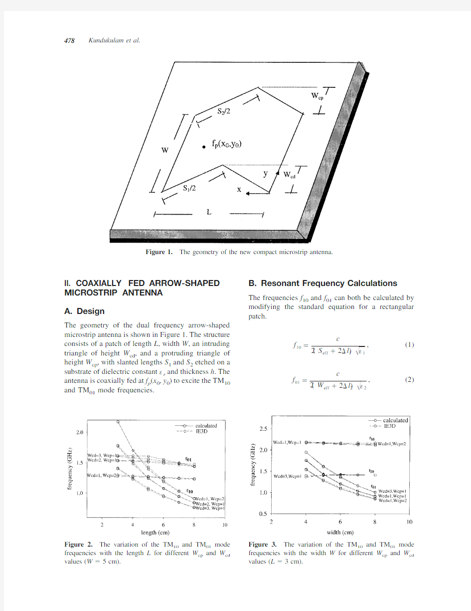
The geometry of the dual frequency arrow-shaped microstrip antenna is shown in Figure 1.The structure consists of a patch of length L ,width W ,an intruding triangle of height W cd ,and a protruding triangle of height W cp ,with slanted lengths S 1and S 2etched on a substrate of dielectric constant ?r and thickness h .The antenna is coaxially fed at f p (x 0,y 0)to excite the TM 10and TM 01mode frequencies.
B.Resonant Frequency Calculations
The frequencies f 10and f 01can both be calculated by modifying the standard equation for a rectangular patch.
f 10?
c
2?S eff ?2?l 1???1
,(1)
f 01?
c
2?W eff ?2?l 2???2
,
(2)
Figure 1.The geometry of the new compact microstrip
antenna.
Figure 2.The variation of the TM 10and TM 01mode frequencies with the length L for different W cp and W cd values (W ?5
cm).Figure 3.The variation of the TM 10and TM 01mode frequencies with the width W for different W cp and W cd values (L ?3cm).
478Kundukulam et al.
?1?
?r ?12??r ?1
2?1?12h /W ??1/2,(3)
?2?
?r ?12??r ?1
2?1?12h /S ??1/2,(4)
?l 1?
0.412h ??1?0.3??W /h ?0.258?
??1?0.258??W /h ?0.8?,
(5)
?l 2?
0.412h ??2?0.3??S /h ?0.258?
??2?0.258??S /h ?0.8?
,
(6)
where S ?(S 1?S 2)/2.
The effective length S eff and width W eff are calcu-lated as follows for (L ?W ):
S eff ?S 1??0.0001/L ??0.01W ?0.68?W cd ?0.01??0.03?W cp ?0.01?W eff ?W ?0.58W cp ?0.43W cd
?for W cd
/W ?0.5,
S eff ?0.5?S 1?L ??0.4W cd ?0.175W ?0.03?W cp ?0.01?W eff ?0.78W ?0.025W cd ?0.49W cp
?for W cd
/W ?0.5;
(7)
Figure 4.The variation of the TM 10and TM 01mode frequencies with the length L for different dielectric con-stant (?r )and thickness (h )values (W ?5cm,W cp ?1cm,W cd ?1cm).
TABLE I.IE3D and Calculated Resonant Frequencies with Percentage of Error
L ,W ,W cp ,W cd (cm)
h (cm)?r TM 10Mode Frequency (GHz)
TM 01Mode Frequency (GHz)IE3D Calcd Error (%)IE3D Calcd Error (%)3,4,0.5,10.16 4.28 2.159 2.16110.09 1.886 1.88310.153,4,2,10.16 4.28 2.172 2.18950.8 1.547 1.53660.673,5,1,30.16 4.28 1.412 1.40170.73 1.605 1.61750.783,6,2,10.16 4.28 2.163 2.1550.36 1.111 1.0898 1.93,6,1,50.16 4.280.96610.9512 1.54 1.372 1.36180.744,5,1,10.16 4.28 1.691 1.68930.1 1.424 1.41340.744,7,1,10.16 4.28 1.687 1.6694 1.04 1.035 1.02610.865,6,0.5,10.16 4.28 1.376 1.3750.07 1.245 1.24150.27,5,1,40.16 4.280.74550.7480.34 1.474 1.47380.017,4,2,10.16 4.28 1.038 1.03750.04 1.468 1.46520.195,5,1,10.32 2.2 1.903 1.90020.14 1.903 1.90660.187,5,1,10.32 2.2 1.374 1.4003 1.91 1.862 1.86250.028,5,1,10.32 2.2 1.217 1.2356 1.5 1.847 1.84270.233,5,1,10.08 2.2 2.982 3.00310.7 1.987 1.962 1.256,5,1,10.08 2.2 1.62 1.6394 1.19 1.954 1.933 1.068,5,1,10.08 2.2 1.234 1.24350.76 1.925 1.8962 1.494,5,1,10.06610.2 1.112 1.10260.080.93180.9183 1.443,5,1,40.06610.20.74190.7283 1.9 1.067 1.044 1.873,5,1,1
0.066
10.2
1.425
1.4126
0.87
0.9389
0.9218
1.85
Compact Dual Frequency Microstrip Antenna 479
and for (L ?W ):
S eff ?S 1?2.3?L ?2W ?0.0046/L ?W cd ?0.00006/L
?0.1?W cp ?0.01?,
for W cd /W ?1;W eff ?W ?0.58W cp ?0.43W cd ?0.0023?L ?W ?/W ,
for W cd /W ?0.5;
W eff ?0.78W ?0.025W cd ?0.49W cp ?0.0025W cd /W
?0.17?L ?W ?0.01?,
for W cd /W ?0.5.
(8)
https://www.sodocs.net/doc/2615481955.html,parison of Calculated and IE3D Results
The results obtained by using eqs.(1)and (2)and an IE3D simulation for various lengths of arrow-shaped antennas for different combinations of W cd and W cp values are shown in Figure 2.Note from the graph that the f 10mode frequency varies rapidly and the f 01frequency remains almost constant for particular W cd and W cp values.The theoretical and simulated results using IE3D are in very good agreement.
Figure 3shows the variation of both the frequen-cies versus the width of the patch.The width varia-tions mainly affect the f 01mode frequency,keeping the other almost constant.The results of the variation of the resonant frequencies with different h and ?r combinations are shown in Figure 4.The theoretical results almost follow the IE3D results in all cases.Table I shows the calculated frequencies,IE3D simulated frequencies,and their corresponding per-centage of error for different combinations of W cd ,W cp ,h ,and ?r values.In all these cases,both of the results are found to be in good agreement with an error of less than 2%.
We observed that the TM 10mode frequency varies with the slanted length S 1and TM 01mode frequency with the effective width (dependent on W cd ,W cp ,W )of the patch.The frequency ratio between these two modes can be changed by varying the dimensions W cd and W cp
.
Figure 5.The geometry of the dual port compact microstrip
antenna.
Figure 6.The variation of the TM 10and TM 01mode frequencies with the length L for different dielectric con-stant (?r )and thickness (h )values for the dual port antenna (W ?5cm,W cd ?1cm,W cp ?1cm).
480Kundukulam et al.
When solved for a rectangular patch(W cd?0, W cp?0),the design equations shown above give ex-actly the same results as those obtained from the design equation of a standard rectangular microstrip patch.
III.ELECTROMAGNETICALLY COUPLED DUAL PORT ARROW-SHAPED MICROSTRIP ANTENNA
A.Design
The above antenna is recon?gured using two perpendic-ular microstrip feed lines to eliminate cross talk between the two polarizations and to achieve excellent isolation between the ports.The geometry of the proposed an-tenna is shown in Figure5.The antenna is etched on a dielectric substrate of thickness h2and dielectric con-stant?r2and fed by proximity coupling using two50?perpendicular microstrip lines etched on a substrate of thickness h1and dielectric constant?r1.
B.Resonant Frequency Calculation
The equations given above for the coaxially fed ar-row-shaped microstrip antenna is modi?ed to obtain the frequencies for the dual ports.Here the thickness of the substrate is modi?ed because ofthe effect of another substrate with the microstrip feed line.Hence, the value of h used in the above equations should be replaced by an effective thickness h eff?h1?h2and the dielectric constant?r??r1??r2,where h1and h2 are the thicknesses of the two layers.
https://www.sodocs.net/doc/2615481955.html,parison of Calculated and
IE3D Results
The variation of the two resonant frequencies with the length for different values of h eff and?r as calculated from eqs.(1)and(2)are shown in Figure6.The IE3D curves are given in the?gure to validate the closed-form expressions.Here the theoretical results are in good agreement with the IE3D values with a maxi-mum error of less than2%as shown in Table II. IV.CONCLUSION
The design equations for calculating the TM10and TM01 mode frequencies of an arrow-shaped dual frequency microstrip antenna are presented.The results are com-pared with IE3D simulation results,which show that both are in good agreement with an error of less than 2%.These equations provide a fast and simple method for the design of this compact microstrip antenna. ACKNOWLEDGMENTS
The authors acknowledge the?nancial support from CSIR, Government of India.
REFERENCES
1.IE3D User’s Manual,Release3.Zeland Software,Inc.,
Fremont,CA,2000.
2.I.J.Bahl and P.Bhartia,Microstrip antennas,Artech
House,Norwood,MA,1981.
3.J.George,M.Deepukumar,C.K.Aanandan,P.Mo-
hanan,and K.G.Nair,New compact microstrip antenna, Electron Lett32(1996),508–509.
4.M.Deepukumar,J.George,C.K.Aanandan,P.Mo-
hanan,and K.G.Nair,Broadband dual frequency micros-trip antenna,Electron Lett32(1996),1531–1532.
5.M.Paulson,S.O.Kundukulam,C.K.Aanandan,and P.Mo-
hanan,A new compact dual band dual polarized microstrip antenna,Microwave Opt Technol Lett29(2001),315–317.
6.S.O.Kundukulam,M.Paulson,C.K.Aanandan,and P.
Mohanan,Slot loaded compact microstrip antenna for dual frequency operation,Microwave Opt Technol Lett 31(2001),379–381.
TABLE II.IE3D and Calculated Resonant Frequencies for Dual Port Antenna with Percentage of Error
L,W,W
cp ,W
cd
(cm)h(cm)?
r
TM
10
Mode Frequency(GHZ)TM
01
Mode Frequency(GHZ)
IE3D Calcd Error(%)IE3D Calcd Error(%)
3,5,1,10.16 4.28 2.08 2.107 1.61 1.395 1.4175 1.3 4,5,1,10.16 4.28 1.645 1.669 1.94 1.379 1.4057 1.46 5,5,1,10.16 4.28 1.368 1.3926 1.98 1.363 1.3963 1.61 4,7,1,10.16 4.28 1.633 1.6433 1.48 1.013 1.0280.63 5,7,1,10.16 4.28 1.343 1.3582 1.29 1.008 1.021 1.13 6,7,1,10.16 4.28 1.148 1.1557 1.2 1.003 1.0570.67 3,5,1,10.06610.2 1.409 1.40840.910.93640.92780.04 4,5,1,10.06610.2 1.112 1.1030.80.93640.9220.81 5,5,1,10.06610.20.92630.91430.040.91720.9176 1.29
Compact Dual Frequency Microstrip Antenna481
BIOGRAPHIES
Sona O.Kundukulam was born in India in 1975.She received the M.S.degree in elec-tronic science from Cochin University of Science and Technology (CUSAT),Cochin,India,in 1997.Currently,she is working toward the Ph.D.degree from CUSAT.She is a Senior Research Fellow of the Council of Scienti ?c and Industrial Research (CSIR)for the Government of India.Her research inter-ests include microstrip antennas and dielectric resonator antennas.She has been selected to visit the International Centre for Theoret-ical Physics,Trieste,Italy,under the young students
program.
Manju Paulson was born in India in 1975.She received her M.S.degree in electronic science from CUSAT in 1997.She is cur-rently a Senior Research Fellow of the CSIR.Her research interests are mainly in micros-trip antennas and microwave propagation
studies.
C.K.Aanandan was born in India in 1959.He received the M.S.and Ph.
D.degrees from CUSAT in 1981and 1987,respectively.Cur-rently he is working as a Reader in the De-partment of Electronics,CUSAT.From 1997to 1998he worked at the Centro Studi Propa-gazione e Antenne,Consiglio Nazionale Delle Ricerche,Torino,Italy,under the TRIL program of the International Centre for
Theoretical Physics (ICTP),Trieste,Italy.Dr.Aanandan is cur-rently a regular associate of ICTP.His research interests include microstrip antennas,radar cross section studies,and frequency selective
surfaces.
P.Mohanan was born in India in 1956.He received the Ph.D.degree in microwave an-tennas from CUSAT in 1985.He spent 2years in Bharat Electronics,Ghaziabad,In-dia,as an Engineer in the Antenna Research and Development Laboratory.Currently he is working as a Professor in the Department of Electronics,CUSAT.His areas of re-search activities include microstrip antennas,
dielectric resonator antennas,superconducting microwave anten-nas,leaky-wave antennas,reduction of radar cross sections,and so forth.Dr.Mohanan received the Career Award from the University Grants Commission in Engineering and Technology,Government of India,in 1994.
482Kundukulam et al.
中国姓氏英文翻译大全S-Z
A: 艾--Ai 安--Ann/An 敖--Ao B: 巴--Pa 白--Pai 包/鲍--Paul/Pao 班--Pan 贝--Pei 毕--Pih 卞--Bein 卜/薄--Po/Pu 步--Poo 百里--Pai-li C: 蔡/柴--Tsia/Choi/Tsai 曹/晁/巢--Chao/Chiao/Tsao 岑--Cheng 崔--Tsui 查--Cha 常--Chiong 车--Che 陈--Chen/Chan/Tan 成/程--Cheng 池--Chi 褚/楚--Chu 淳于--Chwen-yu D: 戴/代--Day/Tai 邓--Teng/Tang/Tung 狄--Ti 刁--Tiao 丁--Ting/T 董/东--Tung/Tong 窦--Tou 杜--To/Du/Too 段--Tuan 端木--Duan-mu 东郭--Tung-kuo 东方--Tung-fang E: F:
范/樊--Fan/Van 房/方--Fang 费--Fei 冯/凤/封--Fung/Fong 符/傅--Fu/Foo G: 盖--Kai 甘--Kan 高/郜--Gao/Kao 葛--Keh 耿--Keng 弓/宫/龚/恭--Kung 勾--Kou 古/谷/顾--Ku/Koo 桂--Kwei 管/关--Kuan/Kwan 郭/国--Kwok/Kuo 公孙--Kung-sun 公羊--Kung-yang 公冶--Kung-yeh 谷梁--Ku-liang H: 海--Hay 韩--Hon/Han 杭--Hang 郝--Hoa/Howe 何/贺--Ho 桓--Won 侯--Hou 洪--Hung 胡/扈--Hu/Hoo 花/华--Hua 宦--Huan 黄--Wong/Hwang 霍--Huo 皇甫--Hwang-fu 呼延--Hu-yen I: J: 纪/翼/季/吉/嵇/汲/籍/姬--Chi 居--Chu 贾--Chia 翦/简--Jen/Jane/Chieh 蒋/姜/江/--Chiang/Kwong 焦--Chiao 金/靳--Jin/King 景/荆--King/Ching
图像处理中值滤波器中英文对照外文翻译文献
中英文资料对照外文翻译 一、英文原文 A NEW CONTENT BASED MEDIAN FILTER ABSTRACT In this paper the hardware implementation of a contentbased median filter suitabl e for real-time impulse noise suppression is presented. The function of the proposed ci rcuitry is adaptive; it detects the existence of impulse noise in an image neighborhood and applies the median filter operator only when necessary. In this way, the blurring o f the imagein process is avoided and the integrity of edge and detail information is pre served. The proposed digital hardware structure is capable of processing gray-scale im ages of 8-bit resolution and is fully pipelined, whereas parallel processing is used to m inimize computational time. The architecturepresented was implemented in FPGA an d it can be used in industrial imaging applications, where fast processing is of the utm ost importance. The typical system clock frequency is 55 MHz. 1. INTRODUCTION Two applications of great importance in the area of image processing are noise filtering and image enhancement [1].These tasks are an essential part of any image pro cessor,whether the final image is utilized for visual interpretation or for automatic an alysis. The aim of noise filtering is to eliminate noise and its effects on the original im age, while corrupting the image as little as possible. To this end, nonlinear techniques (like the median and, in general, order statistics filters) have been found to provide mo re satisfactory results in comparison to linear methods. Impulse noise exists in many p ractical applications and can be generated by various sources, including a number of man made phenomena, such as unprotected switches, industrial machines and car ign ition systems. Images are often corrupted by impulse noise due to a noisy sensor or ch annel transmission errors. The most common method used for impulse noise suppressi on n forgray-scale and color images is the median filter (MF) [2].The basic drawback o f the application of the MF is the blurringof the image in process. In the general case,t he filter is applied uniformly across an image, modifying pixels that arenot contamina ted by noise. In this way, the effective elimination of impulse noise is often at the exp ense of an overalldegradation of the image and blurred or distorted features[3].In this paper an intelligent hardware structure of a content based median filter (CBMF) suita ble for impulse noise suppression is presented. The function of the proposed circuit is to detect the existence of noise in the image window and apply the corresponding MF
中国姓氏英语翻译大全
中国姓氏英语翻译大全 A: 艾--Ai 安--Ann/An 敖--Ao B: 巴--Pa 白--Pai 包/鲍--Paul/Pao 班--Pan 贝--Pei 毕--Pih 卞--Bein 卜/薄--Po/Pu 步--Poo 百里--Pai-li C: 蔡/柴--Tsia/Choi/Tsai 曹/晁/巢--Chao/Chiao/Tsao 岑--Cheng 崔--Tsui 查--Cha
常--Chiong 车--Che 陈--Chen/Chan/Tan 成/程--Cheng 池--Chi 褚/楚--Chu 淳于--Chwen-yu D: 戴/代--Day/Tai 邓--Teng/Tang/Tung 狄--Ti 刁--Tiao 丁--Ting/T 董/东--Tung/Tong 窦--Tou 杜--To/Du/Too 段--Tuan 端木--Duan-mu 东郭--Tung-kuo 东方--Tung-fang E: F:
范/樊--Fan/Van 房/方--Fang 费--Fei 冯/凤/封--Fung/Fong 符/傅--Fu/Foo G: 盖--Kai 甘--Kan 高/郜--Gao/Kao 葛--Keh 耿--Keng 弓/宫/龚/恭--Kung 勾--Kou 古/谷/顾--Ku/Koo 桂--Kwei 管/关--Kuan/Kwan 郭/国--Kwok/Kuo 公孙--Kung-sun 公羊--Kung-yang 公冶--Kung-yeh 谷梁--Ku-liang H:
韩--Hon/Han 杭--Hang 郝--Hoa/Howe 何/贺--Ho 桓--Won 侯--Hou 洪--Hung 胡/扈--Hu/Hoo 花/华--Hua 宦--Huan 黄--Wong/Hwang 霍--Huo 皇甫--Hwang-fu 呼延--Hu-yen I: J: 纪/翼/季/吉/嵇/汲/籍/姬--Chi 居--Chu 贾--Chia 翦/简--Jen/Jane/Chieh 蒋/姜/江/--Chiang/Kwong
图像处理外文翻译 (2)
附录一英文原文 Illustrator software and Photoshop software difference Photoshop and Illustrator is by Adobe product of our company, but as everyone more familiar Photoshop software, set scanning images, editing modification, image production, advertising creative, image input and output in one of the image processing software, favored by the vast number of graphic design personnel and computer art lovers alike. Photoshop expertise in image processing, and not graphics creation. Its application field, also very extensive, images, graphics, text, video, publishing various aspects have involved. Look from the function, Photoshop can be divided into image editing, image synthesis, school tonal color and special effects production parts. Image editing is image processing based on the image, can do all kinds of transform such as amplifier, reducing, rotation, lean, mirror, clairvoyant, etc. Also can copy, remove stain, repair damaged image, to modify etc. This in wedding photography, portrait processing production is very useful, and remove the part of the portrait, not satisfied with beautification processing, get let a person very satisfactory results. Image synthesis is will a few image through layer operation, tools application of intact, transmit definite synthesis of meaning images, which is a sure way of fine arts design. Photoshop provide drawing tools let foreign image and creative good fusion, the synthesis of possible make the image is perfect. School colour in photoshop with power is one of the functions of deep, the image can be quickly on the color rendition, color slants adjustment and correction, also can be in different colors to switch to meet in different areas such as web image design, printing and multimedia application. Special effects production in photoshop mainly by filter, passage of comprehensive application tools and finish. Including image effects of creative and special effects words such as paintings, making relief, gypsum paintings, drawings, etc commonly used traditional arts skills can be completed by photoshop effects. And all sorts of effects of production are
库卡工业机器人运动指令入门知识学员必备)
库卡工业机器人运动指令的入门知识问?学完了KUKA机器人的运动指令后,可以了解到哪些? 答(1)通过对机器人几种基本运动指令的学习,能够熟练掌握机器人各种轨迹运动的相关编程操作 (2)通过学习PTP运动指令的添加方法,能够掌握机器人的简单编程 机器人的运动方式: 机器人在程序控制下的运动要求编制一个运动指令,有不同的运动方式供运动指令的编辑使用,通过制定的运动方式和运动指令,机器人才会知道如何进行运动,机器人的运动方式有以下几种: (1)按轴坐标的运动(PTP:Point-toPoint,即点到点) (2)沿轨迹的运动:LIN直线运动和CIRC圆周运动 (3)样条运动:SPLINE运动 点到点运动 PTP运动是机器人沿最快的轨道将TCP从起始点引至目标点,这个移动路线不一定是直线,因为机器人轴进行回转运动,所以曲线轨道比直线轨道运动更快。此轨迹无法精确预知,所以在调试及试运行时,应该在阻挡物体附近降低速度来测试机器人的移动特性。线性运动
线性运动是机器人沿一条直线以定义的速度将TCP引至目标点。在线性移动过程中,机器人转轴之间进行配合,是工具或工件参照点沿着一条通往目标点的直线移动,在这个过程中,工具本身的取向按照程序设定的取向变化。 圆周运动 圆周运动是机器人沿圆形轨道以定义的速度将TCP移动至目标点。圆形轨道是通过起点、辅助点和目标点定义的,起始点是上一条运动指令以精确定位方式抵达的目标点,辅助点是圆周所经历的中间点。在机器人移动过程中,工具尖端取向的变化顺应与持续的移动轨迹。 样条运动 样条运动是一种尤其适用于复杂曲线轨迹的运动方式,这种轨迹原则上也可以通过LIN 运动和CIRC运动生成,但是相比下样条运动更具有优势。 创建以优化节拍时间的运动(轴运动) 1?PTP运动 PTP运动方式是时间最快,也是最优化的移动方式。在KPL程序中,机器人的第一个指令必须是PTP或SPTP,因为机器人控制系统仅在PTP或SPTP运动时才会考虑编程设置的状态和转角方向值,以便定义一个唯一的起始位置。 2?轨迹逼近 为了加速运动过程,控制器可以CONT标示的运动指令进行轨迹逼近,轨迹逼近意味着将不精确到达点坐标,只是逼近点坐标,事先便离开精确保持轮廓的轨迹。
双语:中国姓氏英文翻译对照大合集
[ ]
步Poo 百里Pai-li C: 蔡/柴Tsia/Choi/Tsai 曹/晁/巢Chao/Chiao/Tsao 岑Cheng 崔Tsui 查Cha 常Chiong 车Che 陈Chen/Chan/Tan 成/程Cheng 池Chi 褚/楚Chu 淳于Chwen-yu
D: 戴/代Day/Tai 邓Teng/Tang/Tung 狄Ti 刁Tiao 丁Ting/T 董/东Tung/Tong 窦Tou 杜To/Du/Too 段Tuan 端木Duan-mu 东郭Tung-kuo 东方Tung-fang F: 范/樊Fan/Van
房/方Fang 费Fei 冯/凤/封Fung/Fong 符/傅Fu/Foo G: 盖Kai 甘Kan 高/郜Gao/Kao 葛Keh 耿Keng 弓/宫/龚/恭Kung 勾Kou 古/谷/顾Ku/Koo 桂Kwei 管/关Kuan/Kwan
郭/国Kwok/Kuo 公孙Kung-sun 公羊Kung-yang 公冶Kung-yeh 谷梁Ku-liang H: 海Hay 韩Hon/Han 杭Hang 郝Hoa/Howe 何/贺Ho 桓Won 侯Hou 洪Hung 胡/扈Hu/Hoo
花/华Hua 宦Huan 黄Wong/Hwang 霍Huo 皇甫Hwang-fu 呼延Hu-yen J: 纪/翼/季/吉/嵇/汲/籍/姬Chi 居Chu 贾Chia 翦/简Jen/Jane/Chieh 蒋/姜/江/ Chiang/Kwong 焦Chiao 金/靳Jin/King 景/荆King/Ching
塑壳断路器的选用
塑壳断路器的选用 1.引言 塑料外壳式断路器 以下简称MCCB ,作为低压配电系统和电动机保护回路中的过载、短路保护电器,是应用极广的产品。随着现代科技水平的不断发展,新技术、新工艺、新材料不断出现,断路器的生产工艺及各种材质不断改进,使断路器的性能有了很大的提高,除国际知名品牌,如ABB、施耐德外,国内一些企业也不甘落后,自行开发、研制或引进国外先进技术,并加以消化、吸收,也向市场推出了成熟了的产品 如常熟开关厂的CMl、天津低压开关厂TM30等 。这类产品具有零飞弧、高分断、大容量、进出线方向可以互换、智能型、四极、内部附件结构模块化、安装积木化、体积小型化等特点。实现了MCCB所需的选择性保护功能和多种辅助功能,并带有通信接口,使低压配电系统实现自动化和组网成为可能;降低了低压成套配电装置的动、热稳定性的要求;缩小了成套配电装置的体积;大大地提高了供配电系统和设备运行的可靠性。 然而,目前在一些电气设计方案中,对MCCB的正确合理选用并不尽人意,往往忽略了所选厂家的MCCB规格、型号、附件等其它电气参数,特别是对一些新型MCCB的电气参数理解不透,标注不全、应用类别、使用场合及用途等考虑不周。选用了不合适的MCCB,导致成套厂订货困难,保护的选择性变差,灵敏性,合理性不符合设计规范要求,不但使MCCB 没有物尽所用,反而造成了浪费,降低了配电系统的可靠性,影响了工矿企业的生产和人们的生活。为此,本文结合有关MC—CB的常用参数和国家标准谈谈自己对MCCB正确选用的一些看法。 2.断路器的常用基本相关符号其合义及相互之间的关系 Inm——断路器壳架等级电流 A ,它所指的含义是本断路器内所能安装的最大开关及脱扣器电流值。 In——断路器的额定电流 A ,它所指的含义是该断路器内选用的额定热动型脱扣器电流值,在不可调固定式热脱扣器中In=Ir1。 Ir1——断路器的长延时整定电流 A ,它所指的含义是该断路器的过载保护脱扣器所整定的电流值。 Ir2——断路器的短延时整定电流 A ,它所指的含义是该断路器的短延时脱扣器整定的电流,它的数值在电子可调式脱扣器中为 2~12Irl 左右可调。 Ir3——断路器的瞬时整定电流 A ,它所指的含义是该断路器瞬时脱扣器整定的电流,它的数值在不可调固定式脱扣器中,配电型为5Irl、10Irl两种,电动机保护型为12Ir1,在电子可调式中,为 4~16Irl 左右可调。 Ir4——断路器的单相接地整定电流 A ,它所指的含义是该断路器保护的线路或设备发生单相接地故障时,接地保护脱扣器整定的电流值,它的数值为0.2~0.6Irl 左右可调。 Ire——断路器的漏电动作电流 A ,它所指的含义是该断路器保护的线路或设备发生不正常泄漏电流时,漏电保护脱扣器整定的电流值。它的数值为0.03/0.1/0.3/0.5A几种。 Ir0——断路器预报警动作电流 A ,它所指的含义是该断路器负载电流超出预先设定的电流时,预报警装置发出报警指示信号,它的数值为 0.5~lIr1 左右可调。 Ir2——短延时脱扣器的脱扣时间整定值 s ,可调时间为0.05~0.45s。
图像处理中常用英文词解释
Algebraic operation 代数运算一种图像处理运算,包括两幅图像对应像素的和、差、积、商。 Aliasing 走样(混叠)当图像像素间距和图像细节相比太大时产生的一种人工痕迹。Arc 弧图的一部分;表示一曲线一段的相连的像素集合。 Binary image 二值图像只有两级灰度的数字图像(通常为0和1,黑和白) Blur 模糊由于散焦、低通滤波、摄像机运动等引起的图像清晰度的下降。 Border 边框一副图像的首、末行或列。 Boundary chain code 边界链码定义一个物体边界的方向序列。 Boundary pixel 边界像素至少和一个背景像素相邻接的内部像素(比较:外部像素、内部像素) Boundary tracking 边界跟踪一种图像分割技术,通过沿弧从一个像素顺序探索到下一个像素将弧检测出。 Brightness 亮度和图像一个点相关的值,表示从该点的物体发射或放射的光的量。 Change detection 变化检测通过相减等操作将两幅匹准图像的像素加以比较从而检测出其中物体差别的技术。 Class 类见模或类 Closed curve 封闭曲线一条首尾点处于同一位置的曲线。 Cluster 聚类、集群在空间(如在特征空间)中位置接近的点的集合。 Cluster analysis 聚类分析在空间中对聚类的检测,度量和描述。 Concave 凹的物体是凹的是指至少存在两个物体内部的点,其连线不能完全包含在物体内部(反义词为凸) Connected 连通的 Contour encoding 轮廓编码对具有均匀灰度的区域,只将其边界进行编码的一种图像压缩技术。 Contrast 对比度物体平均亮度(或灰度)与其周围背景的差别程度 Contrast stretch 对比度扩展一种线性的灰度变换 Convex 凸的物体是凸的是指连接物体内部任意两点的直线均落在物体内部。Convolution 卷积一种将两个函数组合成第三个函数的运算,卷积刻画了线性移不变系统的运算。 Corrvolution kernel 卷积核1,用于数字图像卷积滤波的二维数字阵列,2,与图像或信号卷积的函数。 Curve 曲线1,空间的一条连续路径,2 表示一路径的像素集合(见弧、封闭曲线)。 Deblurring 去模糊1一种降低图像模糊,锐化图像细节的运算。2 消除或降低图像的模糊,通常是图像复原或重构的一个步骤。 Decision rule 决策规则在模式识别中,用以将图像中物体赋以一定量的规则或算法,这种赋值是以对物体特征度量为基础的。 Digital image 数字图像 1 表示景物图像的整数阵列,2 一个二维或更高维的采样并量化的函数,它由相同维数的连续图像产生,3 在矩形(或其他)网络上采样一连续函数,并才采样点上将值量化后的阵列。 Digital image processing 数字图像处理对图像的数字化处理;由计算机对图片信息进
塑壳断路器的选用
1.引言 塑料外壳式断路器以下简称MCCB,作为低压配电系统和电动机保护回路中的过载、短路保护电器,是应用极广的产品。随着现代科技水平的不断发展,新技术、新工艺、新材料不断出现,断路器的生产工艺及各种材质不断改进,使断路器的性能有了很大的提高,除国际知名品牌,如ABB、施耐德外,国内一些企业也不甘落后,自行开发、研制或引进国外先进技术,并加以消化、吸收,也向市场推出了成熟了的产品如常熟开关厂的CMl、天津低压开关厂TM30等。这类产品具有零飞弧、高分断、大容量、进出线方向可以互换、智能型、四极、内部附件结构模块化、安装积木化、体积小型化等特点。实现了MCCB所需的选择性保护功能和多种辅助功能,并带有通信接口,使低压配电系统实现自动化和组网成为可能;降低了低压成套配电装置的动、热稳定性的要求;缩小了成套配电装置的体积;大大地提高了供配电系统和设备运行的可靠性。 然而,目前在一些电气设计方案中,对MCCB的正确合理选用并不尽人意,往往忽略了所选厂家的MCCB规格、型号、附件等其它电气参数,特别是对一些新型MCCB 的电气参数理解不透,标注不全、应用类别、使用场合及用途等考虑不周。选用了不合适的MCCB,导致成套厂订货困难,保护的选择性变差,灵敏性,合理性不符合设计规范要求,不但使MCCB没有物尽所用,反而造成了浪费,降低了配电系统的可靠性,影响了工矿企业的生产和人们的生活。为此,本文结合有关MC—CB的常用参数和国家标准谈谈自己对MCCB正确选用的一些看法。 2.断路器的常用基本相关符号其合义及相互之间的关系 Inm——断路器壳架等级电流,它所指的含义是本断路器内所能安装的最大 开关及脱扣器电流值。 In——断路器的额定电流,它所指的含义是该断路器内选用的额定热动型脱 扣器电流值,在不可调固定式热脱扣器中In=Ir1。 Ir1——断路器的长延时整定电流,它所指的含义是该断路器的过载保护脱 扣器所整定的电流值。 Ir2——断路器的短延时整定电流,它所指的含义是该断路器的短延时脱扣 器整定的电流,它的数值在电子可调式脱扣器中为~12Irl左右可调。 Ir3——断路器的瞬时整定电流,它所指的含义是该断路器瞬时脱扣器整定 的电流,它的数值在不可调固定式脱扣器中,配电型为5Irl、10Irl两种,电动机保护型为12Ir1,在电子可调式中,为~16Irl左右可调。 Ir4——断路器的单相接地整定电流,它所指的含义是该断路器保护的线路或设备发生单相接地故障时,接地保护脱扣器整定的电流值,它的数值为0.2~0.6Irl 左右可调。 Ire——断路器的漏电动作电流,它所指的含义是该断路器保护的线路或设 备发生不正常泄漏电流时,漏电保护脱扣器整定的电流值。它的数值为 0.03/0.1/0.3/0.5A几种。 Ir0——断路器预报警动作电流,它所指的含义是该断路器负载电流超出预 先设定的电流时,预报警装置发出报警指示信号,它的数值为~lIr1左右可调。 Ir2——短延时脱扣器的脱扣时间整定值,可调时间为0.05~0.45s。 3.MCCB的额定分断能力、Ics 根据IEC947—2《低压开关设备和控制设备,低压断路器》规范,
库卡工业机器人运动指令入门知识 学员必备
库卡工业机器人运动指令的入门知识 问?学完了的运动指令后,可以了解到哪些? 答(1)通过对机器人几种基本运动指令的学习,能够熟练掌握机器人各种轨迹运动的相关编程操作 (2)通过学习PTP运动指令的添加方法,能够掌握机器人的简单编程 机器人的运动方式: 机器人在程序控制下的运动要求编制一个运动指令,有不同的运动方式供运动指令的编辑使用,通过制定的运动方式和运动指令,机器人才会知道如何进行运动,机器人的运动方式有以下几种: (1)按轴坐标的运动(PTP:Point-toPoint,即点到点) (2)沿轨迹的运动:LIN直线运动和CIRC圆周运动 (3)样条运动:SPLINE运动 点到点运动
PTP运动是机器人沿最快的轨道将TCP从起始点引至目标点,这个移动路线不一定是直线,因为机器人轴进行回转运动,所以曲线轨道比直线轨道运动更快。此轨迹无法精确预知,所以在调试及试运行时,应该在阻挡物体附近降低速度来测试机器人的移动特性。 线性运动
线性运动是机器人沿一条直线以定义的速度将TCP引至目标点。在线性移动过程中,机器人转轴之间进行配合,是工具或工件参照点沿着一条通往目标点的直线移动,在这个过程中,工具本身的取向按照程序设定的取向变化。 圆周运动 圆周运动是机器人沿圆形轨道以定义的速度将TCP移动至目标点。圆形轨道是通过起点、辅助点和目标点定义的,起始点是上一条运动指令以精确定位方式抵达的目标点,辅助点是圆周所经历的中间点。在机器人移动过程中,工具尖端取向的变化顺应与持续的移动轨迹。 样条运动
样条运动是一种尤其适用于复杂曲线轨迹的运动方式,这种轨迹原则上也可以通过LIN运动和CIRC运动生成,但是相比下样条运动更具有优势。 创建以优化节拍时间的运动(轴运动) 1?PTP运动 PTP运动方式是时间最快,也是最优化的移动方式。在KPL程序中,机器人的第一个指令必须是PTP或SPTP,因为机器人控制系统仅在PTP或SPTP运动时才会考虑编程设置的状态和转角方向值,以便定义一个唯一的起始位置。 2?轨迹逼近 为了加速运动过程,控制器可以CONT标示的运动指令进行轨迹逼近,轨迹逼近意味着将不精确到达点坐标,只是逼近点坐标,事先便离开精确保持轮廓的轨迹。 PTP运动的轨迹逼近是不可预见的,相比较点的精确暂停,轨迹逼近具有如下的优势: (1)由于这些点之间不再需要制动和加速,所以运动系统受到的磨损减少。(2)节拍时间得以优化,程序可以更快的运行。 创建PTP运动的操作步骤 (1)创建PTP运动的前提条件是机器人的运动方式已经设置为T1运行方式,并且已经选定机器人程序。
中国姓氏英语翻译大全
中国姓氏英语翻译大全 A: 艾--Ai 安--Ann/An 敖--Ao B: 巴--Pa 白--Pai 包/鲍--Paul/Pao 班--Pan 贝--Pei 毕--Pih 卞--Bein 卜/薄--Po/Pu 步--Poo 百里--Pai-li C: 蔡/柴--Tsia/Choi/Tsai 曹/晁/巢--Chao/Chiao/Tsao 岑--Cheng 崔--Tsui 查--Cha 常--Chiong 车--Che 陈--Chen/Chan/Tan 成/程--Cheng 池--Chi 褚/楚--Chu 淳于--Chwen-yu D: 戴/代--Day/Tai 邓--Teng/Tang/Tung 狄--Ti 刁--Tiao 丁--Ting/T 董/东--Tung/Tong 窦--Tou 杜--To/Du/Too 段--Tuan 端木--Duan-mu 东郭--Tung-kuo 东方--Tung-fang E: F: 范/樊--Fan/Van 房/方--Fang 费--Fei 冯/凤/封--Fung/Fong 符/傅--Fu/Foo G: 盖--Kai 甘--Kan 高/郜--Gao/Kao 葛--Keh 耿--Keng 弓/宫/龚/恭--Kung 勾--Kou 古/谷/顾--Ku/Koo 桂--Kwei 管/关--Kuan/Kwan 郭/国--Kwok/Kuo 公孙--Kung-sun 公羊--Kung-yang 公冶--Kung-yeh 谷梁--Ku-liang H: 海--Hay 韩--Hon/Han 杭--Hang 郝--Hoa/Howe 何/贺--Ho 桓--Won 侯--Hou 洪--Hung 胡/扈--Hu/Hoo 花/华--Hua 宦--Huan 黄--Wong/Hwang 霍--Huo 皇甫--Hwang-fu 呼延--Hu-yen I: J: 纪/翼/季/吉/嵇/汲/籍/姬--Chi
塑壳断路器附件功能与选用
塑壳断路器附件功能与选用 塑壳断路器(以下简称断路器)的附件作为断路器功能的派生和补充,为断路器增加了更多的控制手段,同时也扩大了保护功能。因此,目前已经成为断路器不可分割的一个重要部分。 1 断路器附件的种类 分为机内附件和机外附件两类。 机内附件是安装在断路器内部的附属装置,包括分励脱扣器、欠电压脱扣器、辅助开关和报警开关等四种。机外附件则是安装在断路器外部的附属装置,包括辅助手柄、外部操作手柄、电操机构、手柄闭锁装置、机械联锁装置、电气联锁装置、板后接线装置、插入式安装台和辅助接点装置等。 2 表示断路器状态的附件 辅助开关和报警开关的区别在于: 辅助开关主要用于断路器的分合状态的显示,通过断路器的分合对其他相关电器实施控制或联锁,报警开关主要用于断路器因故障而断开时的状态显示,在断路器负载发生故障时及时向其他相关电器实施控制或联锁。 3 实现断路器欠电压保护功能的附件 欠电压脱扣器是一种保护性附件,当电源电压下降到欠电压脱扣器额定电压的35%~70%时,欠电压脱扣器能使断路器脱扣;当电源电压低于欠电压脱扣器额定电压的35%时,欠电压脱扣器能保证断路器不合闸;当电源电压高于欠电压脱扣器额定电压的85%时,欠电压脱扣器能保证断路器正常工作。 4 实现断路器操作功能的附件 (1)分励脱扣器是一种实现断路器的远距离分闸的附件,通常用于应急状态下对断路器进行远距离分闸操作和作为漏电继电器等保护电器的执行元件。 (2)电操机构也是一种远距离操作断路器的机外附件,既可用来实现断路器的远距离分闸操作,也能实现断路器的合闸操作。 (3)辅助手柄一般用于600A及以上的大容量断路器上,进行手动分合闸操作。 (4)外部操作手柄是一种具有将断路器的上下扳动操作转换成旋转操作功能的机外附件。 5 实现断路器锁定功能和联锁功能的附件 (1)手柄闭锁装置是一种能使断路器操作手柄可靠地处于打开或闭合位置(即分闸或合闸锁定),而在机械上并不影响断路器自由脱扣的保护装置。 (2)机械联锁装置也是一种保护装置,主要用于双电源供电电路中两台断路器不可同时通电的场合。 (3)电气联锁装置(也称自动电源切换装置)为自动实现切换的双电源保护装置。 6 实现断路器多种安装接线方式的附件
图像处理英文翻译
数字图像处理英文翻译 (Matlab帮助信息简介) xxxxxxxxx xxx Introduction MATLAB is a high-level technical computing language and interactive environment for algorithm development, data visualization, data analysis, and numeric computation. Using the MATLAB product, you can solve technical computing problems faster than with traditional programming languages, such as C, C++, and Fortran. You can use MATLAB in a wide range of applications, including signal and image processing, communications, control design, test and measurement, financial modeling and analysis, and computational biology. Add-on toolboxes (collections of special-purpose MATLAB functions, available separately) extend the MATLAB environment to solve particular classes of problems in these application areas. The MATLAB system consists of these main parts: Desktop Tools and Development Environment This part of MATLAB is the set of tools and facilities that help you use and become more productive with MATLAB functions and files. Many of these tools are graphical user interfaces. It includes: the
中国姓氏英文翻译大全
中国姓氏英文翻译大全 A: 艾--Ai 安--Ann/An 敖--Ao B: 巴--Pa 白--Pai 包/鲍--Paul/Pao 班--Pan 贝--Pei 毕--Pih 卞--Bein 卜/薄--Po/Pu 步--Poo 百里--Pai-li C: 蔡/柴--Tsia/Choi/Tsai 曹/晁/巢--Chao/Chiao/Tsao 岑--Cheng 崔--Tsui 查--Cha 常--Chiong 车--Che 陈--Chen/Chan/Tan 成/程--Cheng 池--Chi 褚/楚--Chu 淳于--Chwen-yu D: 戴/代--Day/Tai 邓--Teng/Tang/Tung 狄--Ti 刁--Tiao 丁 --Ting/T 董/东--Tung/Tong 窦--Tou 杜--To/Du/Too 段--Tuan 端木--Duan-mu 东郭--Tung-kuo 东方--Tung-fang E: F: 范/樊--Fan/Van 房/方--Fang 费--Fei 冯/凤/封--Fung/Fong 符/傅 --Fu/Foo G: 盖--Kai 甘--Kan 高/郜--Gao/Kao 葛--Keh 耿--Keng 弓/宫/龚/恭--Kung 勾--Kou 古/谷/顾--Ku/Koo 桂--Kwei 管/关--Kuan/Kwan 郭/国--Kwok/Kuo 公孙--Kung-sun 公羊 --Kung-yang 公冶--Kung-yeh 谷梁--Ku-liang H: 海--Hay 韩--Hon/Han 杭--Hang 郝--Hoa/Howe 何/贺--Ho 桓--Won 侯--Hou 洪--Hung 胡/扈--Hu/Hoo 花/华--Hua 宦--Huan 黄--Wong/Hwang 霍--Huo 皇甫--Hwang-fu 呼延--Hu-yen I: J: 纪/翼/季/吉/嵇/汲/籍/姬--Chi 居--Chu 贾--Chia 翦/简 --Jen/Jane/Chieh 蒋/姜/江/--Chiang/Kwong 焦--Chiao 金/靳--Jin/King 景/荆 --King/Ching 讦--Gan K: 阚--Kan 康--Kang 柯--Kor/Ko 孔--Kong/Kung 寇--Ker 蒯--Kuai 匡--Kuang L: 赖--Lai 蓝--Lan 郎--Long 劳--Lao 乐--Loh 雷--Rae/Ray/Lei 冷--Leng 黎/郦/利/李--Lee/Li/Lai/Li 连--Lien 廖--Liu/Liao 梁--Leung/Liang 林/蔺--Lim/Lin
塑壳断路器的选用
摘要:结合塑壳断路器 MCCB 的常用电气参数,提出了各种MCCB的正确选用方法,指出了各电气参数之间的内在联系。 关键词:塑壳断路器选择使用 1.引言 塑料外壳式断路器以下简称MCCB ,作为低压配电系统和电动机保护回路中的过载、短路保护电器,是应用极广的产品。随着现代科技水平的不断发展,新技术、新工艺、新材料不断出现,断路器的生产工艺及各种材质不断改进,使断路器的性能有了很大的提高,除国际知名品牌,如ABB、施耐德外,国内一些企业也不甘落后,自行开发、研制或引进国外先进技术,并加以消化、吸收,也向市场推出了成熟了的产品如常熟开关厂的CMl、天津低压开关厂TM30等。这类产品具有零飞弧、高分断、大容量、进出线方向可以互换、智能型、四极、内部附件结构模块化、安装积木化、体积小型化等特点。实现了MCCB所需的选择性保护功能和多种辅助功能,并带有通信接口,使低压配电系统实现自动化和组网成为可能;降低了低压成套配电装置的动、热稳定性的要求;缩小了成套配电装置的体积;大大地提高了供配电系统和设备运行的可靠性。 然而,目前在一些电气设计方案中,对MCCB的正确合理选用并不尽人意,往往忽略了所选厂家的MCCB规格、型号、附件等其它电气参数,特别是对一些新型MCCB的电气参数理解不透,标注不全、应用类别、使用场合及用途等考虑不周。选用了不合适的MCCB,导致成套厂订货困难,保护的选择性变差,灵敏性,合理性不符合设计规范要求,不但使MCCB没有物尽所用,反而造成了浪费,降低了配电系统的可靠性,影响了工矿企业的生产和人们的生活。为此,本文结合有关MC—CB的常用参数和国家标准谈谈自己对MCCB正确选用的一些看法。 2.断路器的常用基本相关符号其合义及相互之间的关系 Inm——断路器壳架等级电流 A ,它所指的含义是本断路器内所能安装的最大开关及脱扣器电流值。 In——断路器的额定电流 A ,它所指的含义是该断路器内选用的额定热动型脱扣器电流值,在不可调固定式热脱扣器中In=Ir1。
(完整版)KUKA简单操作说明书
KUKA简单操作说明书 一、KUKA控制面板介绍 1、示教背面 在示教盒的背面有三个白色和一个绿色的按钮。三个白色按钮是使能开关(伺服上电),用在T1和T2模式下。不按或者按死此开关,伺服下电,机器人不能动作;按在中间档时,伺服上电,机器人可以运动。绿色按钮是启动按钮。 Space Mouse为空间鼠标又称6D鼠标。 2、示教盒正面
急停按钮: 这个按钮用于紧急情况时停止机器人。一旦这个按钮被按下,机器人的伺服电下,机器人立即停止。 需要运动机器人时,首先要解除急停状态,旋转此按钮可以抬起它并解除急停状态,然后按功能键“确认(Ackn.)”,确认掉急停的报警信息才能运动机器人。 伺服上电: 这个按钮给机器人伺服上电。此按钮必须在没有急停报警、安全门关闭、机器人处于自动模式(本地自动、外部自动)的情况下才有用。 伺服下电: 这个按钮给机器人伺服上电。
模式选择开关: T1模式:手动运行机器人或机器人程序。在手动运行机器人或机器人程序时,最大速度都为250mm/s。 T2模式:手动运行机器人或机器人程序。在手动运行机器人时,最大速度为250mm/s。在手动运行机器人程序时,最大速度为程序中设定的速度。 本地自动:通过示教盒上的启动按钮可以使程序自动运行。 外部自动:必须通过外部给启动信号才能自动执行程序。 退出键: 可以退出状态窗口、菜单等。 窗口转换键: 可以在程序窗口、状态窗口、信息窗口之间进行焦点转换。当某窗口背景呈蓝色时,表示此窗口被选中,可以对这个窗口进行操作,屏幕下方的功能菜单也相应改变。 暂停键: 暂停正在运行的程序。按“向前运行”或“向后运行”重新启动程序。 向前运行键: 向前运行程序。在T1和T2模式,抬起此键程序停止运行,机器人停止。 向后运行键: 向后运行程序。仅在T1和T2模式时有用。 回车键: 确认输入或确认指令示教完成。 箭头键: 移动光标。
相关文档
- 库卡kuka经典编程54737
- KUKA机器人编程手册
- 库卡机器人特殊指令的使用
- 库卡指令参数说明
- KUKA机器人KRC4操作说明书
- KUKA机器人KRC4操作说明书
- KUKA机器人基本指令的使用
- 库卡工业机器人运动指令入门知识学员必备
- 库卡指令参数说明
- 库卡工业机器人运动指令入门知识 学员必备
- 第13课:KUKA机器人IO控制指令与等待功能指令
- 库卡机器人系统参数的设定
- 库卡指令参数说明
- (完整版)KUKA简单操作说明书
- KUKA简单操作说明书
- 库卡机器人基本指令的使用
- KUKA机器人IO控制指令与等待功能指令
- 库卡kuka经典编程
- 库卡机械手操作界面说明书
- 【最新版】KUKA机器人程序命令